Parameters of 3D Model Tree |
  
|
Commands and options for customizing the display of the model tree, are located in the drop-down menu, which can be invoked by pressing the ![]() Parameters button in the tree toolbar:
Parameters button in the tree toolbar:

This drop-down menu is also available under the last item (View) of the contextual menu of tree elements.
When this option is enabled, the panel for searching elements in the tree by keywords is displayed in the toolbar at the top of the tree.

![]()
The command invokes the Parameters dialog, where you can customize colors of text and background for various tree elements.
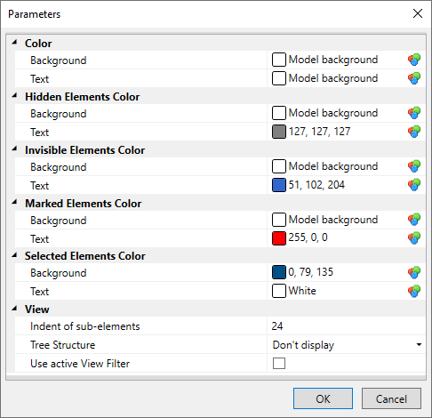

Additionally, the dialog contains the View group of parameters. Its content depends on whether the dialog was called from the 3D model window or from the model tree in the 3D scene.
Following parameters are available in both cases:
•Use active View Filter
The 3D window selector can be adjusted for selecting elements in the model tree. To activate the filter, flag this item in the context menu. When you move the cursor over the items in the tree, only the elements corresponding to the active filter will be highlighted. This checkbox is also available directly in the drop-down menu of tree parameters.
•Indent of sub-elements
Horizontal offset between parent and child elements in the tree in pixels.
If the dialog is invoked for the 3D model window, then the following parameter is additionally available:
•Tree Structure
Allows to set visual representation of the tree structure. The following options are available: don’t display, lines, dots.

If the dialog is invoked for tree in 3D scene, then following parameters are additionally available:
•Blur background borders
Sharpness of transition from color of the scene to color of the tree background.
•Rounding of background box corners
Radius of filleting background rectangles' corners.
This command allows a user to customize information which is displayed in the tree of the 3D model. Upon calling this command, the settings dialog window appears.

The Appearance dialog allows to select data, which will be displayed in the tree for elements of various types. Element Type can be switched using the drop-down menu in the top part of the dialog. The Show list contains data, which is currently displayed in the tree. The Available Data list contains data, which is currently not displayed. Use [<<] and [>>] buttons in the center of the dialog to transfer data between lists. Rows of the Show list can be reordered using the Up and Down buttons. Data, which is displayed top-down in the Show list, will be displayed left to right in the tree. Depending on the selected Element Type following data might be available:
•Name;
•File name;
•Description (according to BoM);
•Part No. (according to BoM);
•ID;
•Recalculation Time in seconds;
•File Path;
•Projecting time (for projections).
If user selects an empty set of data to show, the system uses the default set.
An arbitrary user-defined Text Before and Text After can be added to any row in the Show list, so it will visually separate this data when displayed in the tree.
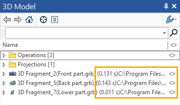
Settings specified in the Appearance dialog are saved in the document file and used upon its subsequent opening.
When the flag is active, fragments connectors are not displayed in the 3D scene.
When this flag is on, the 3D model tree is displayed in the order in which the elements were created.
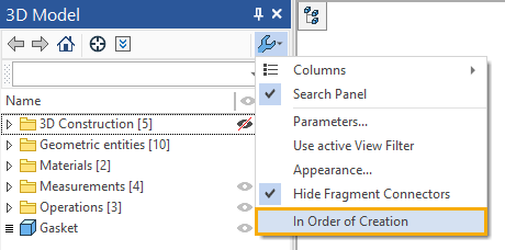
All elements of the 3D model are displayed as root elements in the form of a list in the order in which they were created.
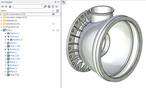
Standard View
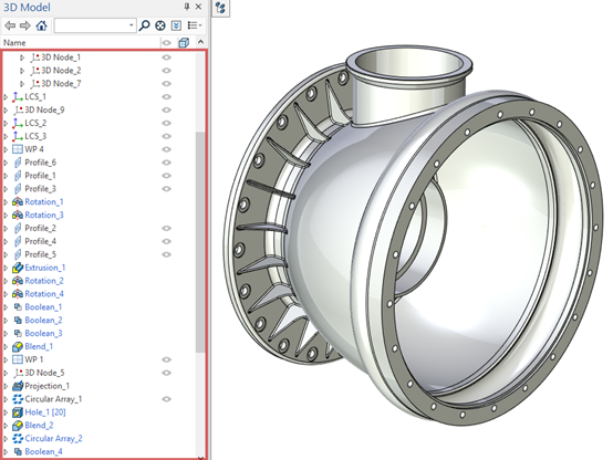
In Order of Creation View