Hole Table |
  
|
Added the new holes table creation command:
Icon |
Ribbon |
|---|---|
|
Title Block > Hole Table > Create |
Keyboard |
Textual menu |
<THS> |
|
It creates a table containing the list of holes and their parameters. Hole table may be useful, when a drawing contains too many holes of various types, so it's hard to fit all necessary dimensions. The table contains data on all cylindrical holes created in various ways (via the ![]() Hole command, via the
Hole command, via the ![]() Extrusion command using
Extrusion command using ![]() Boolean subtraction, holes in imported geometry etc.), as well as data on holes with conical thread created via the
Boolean subtraction, holes in imported geometry etc.), as well as data on holes with conical thread created via the ![]() Hole command. Holes are taken into account, only if they're visible on selected 2D projection.
Hole command. Holes are taken into account, only if they're visible on selected 2D projection.
The command becomes available upon creating at least one 2D projection.
Tables of following types can be created:
•Symbol Table
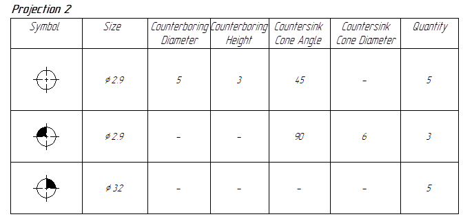
When creating such table, standard symbols are put above the image of each hole on 2D projection. Each symbol corresponds to a particular set of hole's geometrical parameters. the table indicates, which symbol corresponds to which parameters.


Symbol table and 2D projection with corresponding symbols
•Coordinate Table
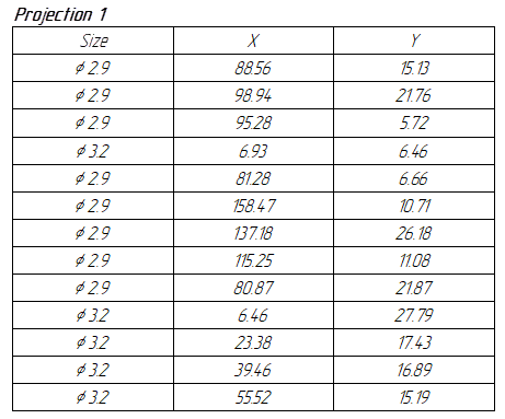
When creating such table, you have to set a local coordinate system (LCS). Then coordinates of each hole's center will be calculated using such LCS and included into the table.


Coordinate table and 2D projection with corresponding LCS
Upon calling the command, perform following actions:
1.Specify a type of table (coordinate or symbol).
2.Select one (for coordinate table) or multiple (for symbol table) 2D projections.
3.Specify a set of columns (optional action).
4.Specify a set of symbols to be used (optional action, available only for symbol table).
5.Confirm the specified parameters (![]() or <Ctrl>+<Enter>).
or <Ctrl>+<Enter>).
6.Set a local coordinate system (only for coordinate table).
7.Place a table in a drawing.
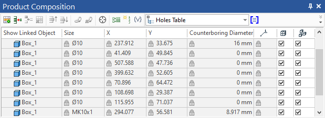
Holes table is a report based on special product composition. If there's no product composition of a Holes Table type in a document, it is created automatically upon calling the holes table creation command. The composition collects data on holes visible on each 2D projection on each page of the document. It recognizes cylindrical holes created in various ways and holes with conical thread created via the ![]() Hole command. If a same hole is visible on multiple projections, then a product composition will contain multiple records based on such hole, depending on the number of projections. Information related to countersink and counterboring is available, only if such elements are created via the
Hole command. If a same hole is visible on multiple projections, then a product composition will contain multiple records based on such hole, depending on the number of projections. Information related to countersink and counterboring is available, only if such elements are created via the ![]() Hole command.
Hole command.
Upon selecting a projection, the holes table creation command collects only those records of product composition, which are related to the selected projection. Holes are taken into account, only if they are visible considering the current projecting direction. Holes represented by hidden lines are ignored.
By default, holes table uses standard report template supplied with T-FLEX CAD. You can create a custom template, if necessary, and replace a template for an existing table in the report parameters dialog.
A holes table product composition may also be created without placing a table in a drawing. It can be done using the following command:
Icon |
Ribbon |
|---|---|
|
Title Block > Hole Table > Hole Table Data |
Keyboard |
Textual menu |
<THS> |
|
Holes table product composition data is handled using the usual T-FLEX CAD product composition management tools.
If you need to exclude from a table some of the holes included into product composition, disable the ![]() Include in report/BOM of current document checkbox in the
Include in report/BOM of current document checkbox in the ![]() Product Composition window for such holes. Upon selecting a record in the
Product Composition window for such holes. Upon selecting a record in the ![]() Product Composition window, its linked hole gets highlighted on 2D projections and in 3D scene. Coordinates of holes are only filled upon placing a coordinate table in drawing, because a coordinate system is not specified until placing a table.
Product Composition window, its linked hole gets highlighted on 2D projections and in 3D scene. Coordinates of holes are only filled upon placing a coordinate table in drawing, because a coordinate system is not specified until placing a table.
