Clip Plane in 3D Scene |
  
|
Clip Plane in 3D Scene |
|
Clip Plane can be used for viewing model elements which are overlapped by other elements. It splits the 3D scene in two areas. One area remains unchanged, another one being clipped. Bodies (surface or solid) and their segments located in the clipped area of the scene are not displayed on the screen. Resulting body section is filled with a color, set in Parameters of this body. Support Geometry is not clipped.
Clipping affects visualization in the 3D window only. No new objects being created in the model and no existing objects being edited upon applying a clip plane. Unlike the 3D section, clip plane cannot be used for creating sectional or cut-out views on the drawing.


Following clip planes can be applied:
•Custom;
•Top View.
Custom clip plane is created upon applying changes in the editing mode using the automenu option ![]() . Other planes are created automatically by the system upon calling a corresponding command.
. Other planes are created automatically by the system upon calling a corresponding command.
Commands for clip planes handling
Icon |
Ribbon |
|---|---|
|
View > Clip Plane > Active |
Keyboard |
Textual menu |
<3CL> |
View > Clip Plane > Active |
The icon of this command is highlighted, when any one of clip planes is active.
If no clip plane is active, calling the command activates Custom clip plane (if it exists) or clip plane In Plane of Screen (if custom plane doesn't exist).
If any one of clip planes is active, calling the command deactivates it.
Icon |
Ribbon |
|---|---|
|
View > Clip Plane > In Plane of Screen |
Keyboard |
Textual menu |
<3CS> |
View > Clip Plane > In Plane of Screen |
Calling the command activates a clip plane which is parallel to the screen plane.
Icon |
Ribbon |
|---|---|
|
View > Clip Plane > Front view |
Keyboard |
Textual menu |
|
View > Clip Plane > Front view |
Calling the command activates a clip plane which is parallel to the standard Front workplane.
Icon |
Ribbon |
|---|---|
|
View > Clip Plane > Right view |
Keyboard |
Textual menu |
|
View > Clip Plane > Right view |
Calling the command activates a clip plane which is parallel to the standard Left workplane but has an opposite normal direction.
Icon |
Ribbon |
|---|---|
|
View > Clip Plane > Top view |
Keyboard |
Textual menu |
|
View > Clip Plane > Top view |
Calling the command activates a clip plane which is parallel to the standard Top workplane.
Icon |
Ribbon |
|---|---|
|
View > Clip Plane > Edit |
Keyboard |
Textual menu |
|
View > Clip Plane > Edit |
The command is available only if some clip plane is active.
Calling the command in the clip plane editing mode restores initial position and orientation of an edited plane.
Calling the command outside the clip plane editing mode enables this mode.
Commands for clip planes handling are also available in the View Toolbar.

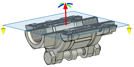
This mode is activated upon activation of a clip plane (of any type). An active clip plane becomes represented by a blue rectangle in the 3D scene. Following manipulators become available:
•Clip plane translation manipulator
It looks like a long red arrow pointing in clip plane normal direction from a center of a plane.
Use it in the similar way as manipulators of 3D elements translation along LCS axis.
•Clip plane rotation manipulators
They look like blue and green arcs located around the tip of the translation manipulator arrow.
Use them in the similar way as manipulators of 3D elements rotation around LCS axis.
•Clipping direction manipulator
It looks like two short yellow arrows located in opposite corners of the plane rectangle.
Arrows are pointing in the non-clipped area of the 3D scene (opposite to the clip plane's normal direction) Click ![]() on an arrow to switch the direction. Switching the clipping direction also switches clip plane's normal direction.
on an arrow to switch the direction. Switching the clipping direction also switches clip plane's normal direction.
Filters toolbar contains filter for selecting faces in the clip plane editing mode. Upon selecting a face in the 3D scene, a clip plane is either coincides with it (if selected face is flat) or becomes tangent to it at an arbitrary point (if selected face is curved).
|
|
When you are done with editing a clip plane, you can use one of the following options:
•Confirm the current orientation using the ![]() automenu option.
automenu option.
Clip plane remains active, but its rectangle and markers disappear. Current position and orientation of a plane are saved as a new Custom clip plane.
•Cancel editing using the ![]() automenu option or by clicking
automenu option or by clicking ![]() .
.
Clip plane becomes inactive. All changes in position and orientation introduced since the last activation are canceled.
•Use the ![]() Edit command to restore initial parameters of the plane.
Edit command to restore initial parameters of the plane.
Moving the clip plane outside editing mode.
Active clip plane can be moved along its normal direction without calling any command. Drag the mouse back or forward while holding ![]() +<Ctrl>+<Shift>.
+<Ctrl>+<Shift>.

