Contour Twist in Sweep |
  
|
One can define additional contour twist along the sweeping trajectory path.
The rotation angle of the intermediate sections can be defined by table or by using additional geometry – a guide path or surface. This approach allows quite different ways of calculating the contour rotation angle.

When using a table for defining twist, rotation by the specified angle of each intermediate section is done about the Z-axis of the calculated coordinate system. The table appears as a set of trajectory points, whose position is defined in percent of the trajectory length, with a fixed value of rotation angle entered against each point. When setting up the table of rotation angles, one can use special manipulators. This functionality is convenient, for example, for creating sweeps with the surface twisted as a spiral.
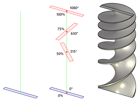
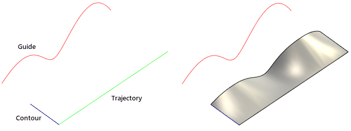
The choice of a path or surface is determined by the specifics of a particular task. For example, if the contour is expected to trace a specified curve throughout sweeping, use a guiding path.
Alternatively, if one needs to create an auxiliary surface touching another surface, staying tangential to that other one, then a surface can be selected for the swept contour orientation. In this way, the tangency condition will be maintained between any intermediate section and the surface.
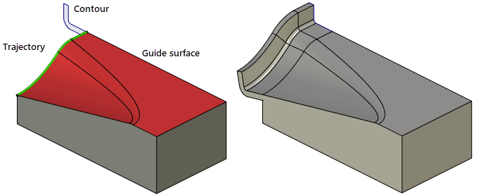
When creating bodies using contour twisting (defined by a guide or surface), make sure of the correct original position of the contour. Thus, in the first example the contour must be originally directed towards the start point of the additional guide. In the second example, the contour shall make tangential transition to the adjacent surface in the original position.
The system uses an additional guide or surface for calculating auxiliary vectors defining a rotation angle for each intermediate section. The rotation angle is calculated as the angle between the directions of the auxiliary vector at the start point of the trajectory and at the current point, for each intermediate section. If the calculated auxiliary vector does not lie in the X-Y plane of the coordinate system of an intermediate section, its projection on that plane will be used.
When a surface is used for calculating the auxiliary vector, its direction is calculated in a general case as follows. A point is identified on the surface that is nearest to the origin of the coordinate system of an intermediate section. The sought direction is a tangency direction constructed at this point. Therefore, best results are achieved when the used surface is closest to the trajectory. In this case, the trajectory can be defined by using, for example, edges of the surface.
If a guide is used for calculating rotation angles of intermediate sections, you can select one of the four methods for calculating the auxiliary vector. The methods for calculating auxiliary vectors by additional guides are described in a separate topic (see below).
Defining contour twist
Contour twist can be defined by a table or by using auxiliary geometry. Let's review all approaches.
Twist definition by table
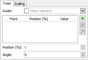
Twist is defined with the help of the controls on the tab Twist of the parameters window.
To enter new contour twist parameters, press the button ![]() . The first time you push it, two special entries are created, Start and End. Subsequent pushes add new intermediate points along the trajectory. Numerical data for each defining point is entered in the parameters window. Each point position is defined in percent of the trajectory length. The section rotation angle is entered in the Twist box, in degrees. To delete a defining point, select it, and then press the button
. The first time you push it, two special entries are created, Start and End. Subsequent pushes add new intermediate points along the trajectory. Numerical data for each defining point is entered in the parameters window. Each point position is defined in percent of the trajectory length. The section rotation angle is entered in the Twist box, in degrees. To delete a defining point, select it, and then press the button ![]() .
.
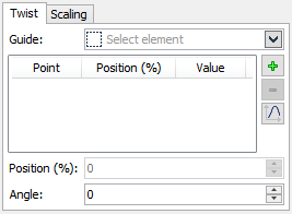
Position of the intermediate points may be specified with the help of a graph. Use ![]() button in the parameters window for this purpose. This button will open the graph editing window. The range of definition by X is 0-100 corresponding to the percentage from the length. The value area is not limited. See more details on operations with graphs in chapter Graphs.
button in the parameters window for this purpose. This button will open the graph editing window. The range of definition by X is 0-100 corresponding to the percentage from the length. The value area is not limited. See more details on operations with graphs in chapter Graphs.
To facilitate definition of twist parameters, auxiliary elements are displayed in the scene – manipulators and decorations.
A decoration is an image of an intermediate section for each defining point, together with an arrow specifying the direction and the rotation angle. Arrows are positioned along a spiral, showing the full rotation angle. This is convenient when the rotation angle exceeds 360 degrees. Decorations of an inactive point are drawn in the yellow color, while the decorations of the point being currently manipulated – in the red.
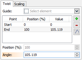
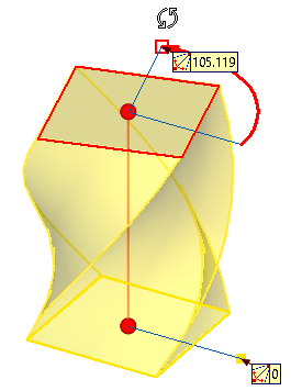
The manipulator is a pair of blue segments indicating the zero angle and the current angle. There are two handles at the ends of one manipulator segment. Dragging those by the mouse with the depressed bottom ![]() modifies the value of the rotation angle and the point position on the path. As the pointer approaches a manipulator handle, it assumes a specific shape.
modifies the value of the rotation angle and the point position on the path. As the pointer approaches a manipulator handle, it assumes a specific shape.
Use of auxiliary geometry for defining twist

Any object with wire geometry can be used as a guide.
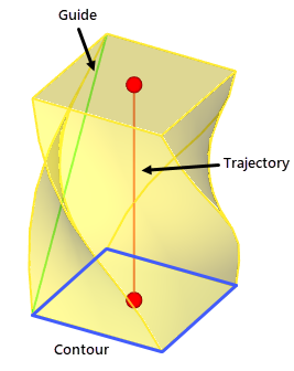
After selecting a guide, the dialog in the parameters window is automatically switched to the display of the pull-down list from which the method of calculation of rotation vector can be selected.
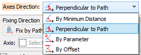
You can choose from four options:
•By Minimal distance
•Perpendicular to path
•By parameter
•By offset.
For more information on the Axes Direction, see Methods for Calculating Auxiliary Vectors by Guides.
The surface can be defined by a face, a surface 3D profile or a surface operation. When using auxiliary geometry, manipulators and decorations are not available.