Correction of Contour Location in Sweep |
  
|
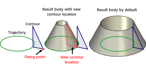
The original contour position can be additionally corrected by selecting one or three additional 3D points.

The correction points can be 3D nodes, vertices, LCS, etc.
Fixing points

One point defines the contour snapping to the start of the path. Contour orientation in this case depends on the selected orientation method. If the option Profile is perpendicular to path is set, the plane of the flat profile is reoriented orthogonal to the path at the start point. When using non-flat contours, the system automatically calculates some "mean normal" that is used for orienting the contour "plane". If the option Profile is parallel to source profile is set, the contour is moved to the start point of the trajectory path by parallel translation.
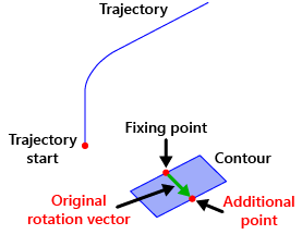
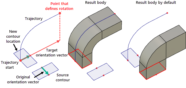
Additional point end Point that defines rotation
In some cases, one point may not be enough for correcting the original contour position since it does not fix the contour rotation about its normal. One can select two additional points in order to specify additional contour rotation about the normal. The second selected point, together with the first one, will determine the original orientation vector (similar to a 2D fragment fixing vector).

The third selected point, together with the start of the trajectory, will define the target orientation vector. The projection of this vector on the plane of the contour will determine the angle of additional rotation of the contour. If a non-flat contour is used, the plane of the contour is determined by the calculated mean normal.

When using non-flat contours, even three-point contour positioning does not guarantee the expected result. In such a case, we recommend setting up the desired contour orientation before starting the operation "Sweep". For example, one can create the contour in the desired position from the beginning or, if that is not feasible, use coordinate system-based copying.