Create Spring |
  
|
The detailed information about geometrical meaning of undermentioned parameters is available in the Main Concepts of Spring chapter.
Creating a spring
To create a spring, do the following steps:
2. Define spring main parameters (optional).
3. Select the start point for the spring profile starting location (optional).
4. Define parameters of compression and grinding of spring ends (optional).
5. Apply aligning with starting or ending point of an axis (optional).
6. Define parameters of a Boolean operation (optional).
7. Confirm operation creation ![]() .
.
The start point of the spring axis is defined by the following automenu option:
|
<F> |
Select starting Point of Axis |
The end point of the axis is selected option:
|
<S> |
Select ending Point of Axis |
The options activate one after another. Selected objects are highlighted in the 3D scene. Once the second point is selected, the following preview of the spring is displayed:
|
1 - Starting point of axis 2 - Ending point of axis 3 - Axis 4 - Helical curve 5 - Profile at start 6 - Profile at end 7 - Radius of profile 8 - Starting radius of helical curve |
At this stage, you can already complete the spring operation by pressing ![]() in the header of the parameters window or in the automenu.
in the header of the parameters window or in the automenu.
Spring operation parameters definition
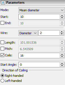
Following parameters can be defined in the Parameters tab of the command parameters window:

The Mode drop-down list contains following options of spring's helical curve diameter/radius calculation:
•Mean radius;
•Mean diameter;
•Inner diameter;
•Outer diameter.
Depending on the selected option, Start and End input boxes could be used to define a corresponding radius or diameter of a helical curve at the starting and ending points of an axis.
The cylindrical spring is created by default, so the End input box is inactive and the radius/diameter is constant along the spring length. Enable the checkbox for the End parameter, if you need to define its value. In this case, the radius/diameter varies linearly along the spring length from Start to End value.
The diameter or radius of a spring's wire can be defined in the Wire input box. Type of parameter is selected in the adjacent drop-down list.
Length, Pitch and Coils input boxes are located below the Wire. By default, only number of Coils can be edited, while Length and Pitch are calculated automatically. If you need to defined any of these parameters manually, enable the checkbox located to the left side of parameter's name. The system disables one of the two enabled parameters automatically if you enable the third one.
The Start Angle parameter defines an angle between wire profile's actual and default starting positions or between actual starting position and a point that defines profile starting location.
Winding direction can be selected using the Direction of Coiling switch. Right-handed - clockwise, Left-handed - counterclockwise.
Selection of the start point for spring profile position
The start point of the spring profile can be specified using the following automenu option (the option activates upon selecting the second axis point):
|
<B> |
Select 3D Node as profile starting location |
To undo a 3D point selection, simply select another one using the same option, or cancel the selection by the option:
|
<K> |
Delete starting 3D Node |
The profile will then revert to its original position. You can enter a numerical value of the angle between profile's actual starting position and a point that defines profile starting location in the Start Angle input box (the Parameters tab of the command parameters window).
Defining compression and grinding of spring ends
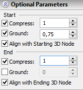
Parameters for compression and grinding of end coils of the spring are defined in the Optional Parameters tab of the command parameters window. To compress coils at the spring start, enable the Compress checkbox in the Start group of parameters and type in the adjacent input box the desired number of coils. Enabling the Ground checkbox in the Start group of parameters allows to define depth of spring start grinding measured in portions of wire diameter.
The compression and grinding parameters at the end of the spring are defined in a similar way using checkboxes in the End group of parameters.

Spring alignment by start or end point
To align the spring by the start or end point, enable the Align with Starting 3D Node or the Align with Ending 3D Node checkbox in the command parameters window. In the case of ambiguity (when both flags are set), the system aligns the spring by the start point.
Using created body in Boolean operation
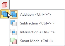
Options for Boolean operation creation are available in lower part of the automenu.
Information about these options can be found in the Using Boolean Operation when Creating Other Operations section.

See also: