Custom Hatch Patterns |
  
|
Custom Hatch Patterns |
|
T-FLEX CAD allows creating custom hatch patterns. T-FLEX CAD hatch pattern may be described using one of the following methods:
1.Using a *.pat-file. This is the AutoCAD hatch patterns description format. So, if a desired pattern is not available, it can be created by the user or copied from AutoCAD system, if you have AutoCAD installed. Name and location of the *.pat-file are set in system options (Options > Files > Hatch Pattern Files). The tcad.pat file located in the ...Program folder is used by default (if T-FLEX CAD is installed in default folder then the full path to the file is C:/Program Files/T‑FLEX Parametric CAD 17/Program/tcad.pat). This file contains various standard and non-standard hatch patterns. The instructions on creating a custom pattern using this method of description can be found in the AutoCAD documentation.
2.Using a *.grb-file. This is a T-FLEX CAD drawing creating in compliance with special rules. The file should be put into the ...Program/HatchPatterns folder (if T-FLEX CAD is installed in default folder then the full path to the folder is C:/Program Files/T‑FLEX CAD 17/Program/HatchPatterns). Upon restarting T-FLEX CAD, the new pattern will appear in the list of patterns in the Hatch command. In order to delete a custom hatch pattern, delete its file from the ...Program/HatchPatterns folder and restart T-FLEX CAD. Rules of creating custom hatch patterns using this method are described below.
Creating Hatch Pattern
A pattern file is a T-FLEX CAD drawing complying with certain rules. It must contain the image of the hatch pattern composed of nodes, graphic lines, text and hatches, as well as construction elements. The starting point of the hatch is defined by a special node named Center. This node is mandatory in the hatch pattern.
To make a given pattern repeatable multiple times when filling the hatch contour, additional named nodes must be defined in the pattern that would define the direction and step of the pattern repetition. The node defining the first hatch direction must be named StepX; the node defining the second direction – StepY. The direction-defining nodes are optional. If either of them is not defined, the pattern will be drawn just once in the respective direction.
Working with Custom Hatches
When using a custom hatch pattern in a document, it is saved within that document. Relation with the source *.grb-file is lost at this point. Therefore, when porting a document file to a computer without the given hatch pattern, the image does not get lost.
When porting a document containing custom hatch patterns to a computer with existing hatch type pattern under the same name, the hatch image stays unchanged in the form of the image saved in the document. To update a hatch image, you would need to re-select its pattern. To make an update, all you need is to bring up the parameters dialog for one of the hatches and confirm the existing value. New hatches of the same type that will be created in this document will take on the current pattern.
Example of Creating Simple Hatch Pattern
To create a custom hatch pattern, let's open a new document (the Create New Drawing command).
In the opened document, create the image of a hatch pattern as shown in the figure below. Make sure to put an additional node on the drawing, named Center, which is mandatory for a hatch pattern.
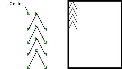
The drawing created this way can already be identified by the system as a custom hatch pattern. All that needs to be done is saving the file into the ...Program/HatchPatterns folder (for example, under the name Custom hatch example.grb) and restart T-FLEX CAD.
However, since no direction nodes are defined in the pattern, an actual hatch created from this pattern will contain just a single instance of the pattern image.
To make the image of the pattern repeatable in one direction, you would need to create the respective named node in the pattern, as, for example, StepX. The position and step of the node will define the step and repetition direction of the pattern image.


Two named nodes – StepX and StepY - would allow defining repetition of the pattern image in both directions. By varying the positions of the directional nodes in relation to the Center node, you can obtain various hatch appearances all based on the same image.


Example of Creating "Wood" Hatch
The custom hatch patterns creation mechanism allows creating even more complex hatches, for example, a woody hatch. To create this type of a hatch, a pattern was created as shown in the figure below. An appropriately arranged placement of directional nodes yields a hatch imitating wood texture.
