System Options > Files |
  
|

In this tab you can change paths to prototype files used, when creating a new T-FLEX CAD document, and to files, which store parameters of various drawing elements. A path can be typed in via keyboard or specified using the ![]() button located to the right of the path's input box. Without T-FLEX DOCs integration this button instantly invokes the standard Windows file selection dialog. Within the integration mode this button invokes a drop-down menu containing following options:
button located to the right of the path's input box. Without T-FLEX DOCs integration this button instantly invokes the standard Windows file selection dialog. Within the integration mode this button invokes a drop-down menu containing following options:
![]() Open...
Open...
Selecting a local file using standard Windows file selection dialog, same as thew one used without DOCs integration.
![]() Open from T-FLEX DOCs...
Open from T-FLEX DOCs...
Selecting a file from DOCs ![]() Files dataset using the standard DOCs file selection dialog.
Files dataset using the standard DOCs file selection dialog.
Path to any file on this tab can be specified in one of the following formats:
•Full path
Example: C:\Program Files\T-FLEX Parametric CAD 17\Program\Template\ISO 3D Model.GRB
A path to any local file can be specified in this format. It is used by default, when selecting a file in standard Windows file selection dialog.
•File name
Example: Annotation.grn
This format can be used for pointing to a file stored in the ...T-FLEX Parametric CAD 17\Program folder. An extension should be specified for prototypes. For other files extension is not specified.
•Path relative to a library
Example: <Titleblk>ISO Title Block.grb
Angle brackets contain a name of a folder located within one of the open library configurations, the rest of the path is a file name.
•Path relative to the T-FLEX DOCs ![]() Files dataset
Files dataset
Example: <*T-FLEX DOCs*>Service Files\Report Templates\ISO_BOM.grb
The <*T-FLEX DOCs*> element refers to the ![]() Files dataset, next a path to a file within dataset's folders structure is specified.
Files dataset, next a path to a file within dataset's folders structure is specified.
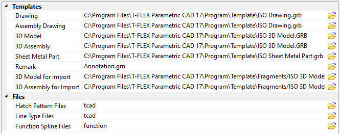
Templates
Paths to following standard prototypes are set here:
•Drawing
Prototype to be used in the Drawing command.
•Assembly Drawing
Prototype to be used in the Assembly Drawing command.
•3D Model
Prototype to be used in the 3D Model command.
•3D Assembly
Prototype to be used in the 3D Assembly command.
•Sheet Metal Part
Prototype to be used in the Sheet Metal Part command.
•Remark
Prototype to be used in the Remark command.
•3D Model for Import, 3D Assembly for Import
Prototypes to be used in the Import command.
By default, Drawing, Assembly Drawing, 3D Model, 3D Assembly, Sheet Metal Part and Import commands use prototypes from the common list of prototypes. Information on the list and custom prototypes creation can be found in the description of the ![]() Save as Prototype command.
Save as Prototype command.
Files
Hatch Pattern Files. The system uses hatch pattern files corresponding to the respective AutoCAD *.PAT files. The file TCAD.PAT, included with the system installation, defines the hatch filling patterns. You can define any hatch pattern file of your own.
Line Type Files. The system has several built-in line types (continuous, thin, waves). The rest of types are defined by the line type file. The system uses the file TCAD.LIN. Its format complies with the line type files of the AutoCAD system. You can define any type file of your own.
Function Spline Files. This special file contains data for setting up the ![]() Function Spline parameters dialog. To create new functions, modify the standard file named FUNCTION.DAT or create a new file with the similar structure, and specify path to it in this box.
Function Spline parameters dialog. To create new functions, modify the standard file named FUNCTION.DAT or create a new file with the similar structure, and specify path to it in this box.