Limitations in Arrays of 3D Elements |
  
|
The interface of defining limitations is described below. The main concepts of limitations are described in the Limitations and Exclusions in Arrays of 3D Elements section.

The Dynamic preview ignores limitations. Use the Preview of Operation Result instead.
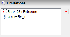
The array creation command's window contains the Limitations tab, if limitations are applicable to the selected type and class of arrays. This tab contains the list of limiting elements. In order to add an limiting element, you need to activate ![]() the list or the corresponding automenu option:
the list or the corresponding automenu option:
|
<1> |
Select limiting elements |
Activation of the list in the parameters window activates the automenu option and vice versa. In result, filters for selecting elements capable of defining a ![]() geometrical surface (
geometrical surface (![]() 3D profiles,
3D profiles, ![]() operations,
operations, ![]() faces,
faces, ![]() worksurfaces) become active on the filter toolbar, so you can sequentially select
worksurfaces) become active on the filter toolbar, so you can sequentially select ![]() any number of suitable elements in the 3D scene or in the model tree. A type icon of a selected element, its name and name of its parent operation in case of selecting a geometric entity are displayed in the Limitations list. Selected elements are highlighted in the 3D scene.
any number of suitable elements in the 3D scene or in the model tree. A type icon of a selected element, its name and name of its parent operation in case of selecting a geometric entity are displayed in the Limitations list. Selected elements are highlighted in the 3D scene.
In order to cancel the selection of one of the selected elements, you need to click ![]() it in the list and use the
it in the list and use the ![]() Delete button located to the right side of the list.
Delete button located to the right side of the list.
Defining the limitation axis by a single 3D element can be done, using the following automenu option:
|
<2> |
Select auxiliary direction of limits |
This option enables filters for selecting ![]() directions on the filter toolbar, so you can select
directions on the filter toolbar, so you can select ![]() a suitable element in the 3D scene or in the model tree. The selected element is highlighted in the 3D scene but is not displayed in the command's parameters window.
a suitable element in the 3D scene or in the model tree. The selected element is highlighted in the 3D scene but is not displayed in the command's parameters window.
Defining the limitation axis by two points can be done, using following automenu options:
|
<3> |
Select first point of auxiliary direction of limits |
|
<4> |
Select second point of auxiliary direction of limits |
This option enables filters for selecting ![]() points on the filter toolbar, so you can select
points on the filter toolbar, so you can select ![]() a suitable element in the 3D scene or in the model tree. The selected element is highlighted in the 3D scene but is not displayed in the command's parameters window. The option for selecting a second point becomes available upon selecting a first point.
a suitable element in the 3D scene or in the model tree. The selected element is highlighted in the 3D scene but is not displayed in the command's parameters window. The option for selecting a second point becomes available upon selecting a first point.
Regardless of whether the limitation axis was defined by a single element or by two points, you can re-define the direction by selecting objects again, using the same automenu options, or cancel the selection, using the following option:
|
<5> |
Cancel selection of auxiliary direction of limits |