Limitations and Exclusions in Arrays of 3D Elements |
  
|
Limitations and exclusions are used to exclude some of the created copies from an array.
Main concepts of limitations in arrays of 3D elements are described below. The interface is described in the Limitations in 3D Arrays section.
Setting a limitation means defining a subset of the 3D space to which copies creation is limited – limitation scope. When in this mode, all copies that are created per the main array parameters are checked by the system for falling in the limitation scope. If a copy fully falls within the scope, it will be included in the resulting array. If a copy is located outside the limitation scope or fits in but partially, it is not included in the resulting array.
Limitations are not available with all classes of construction element arrays, as well as with any parametric arrays and arrays by table. Arrays by pattern inherit limitations from patterns.
The limitation scope is defined by a 3D element, which has a length and width, but doesn't have a thickness – a face, 3D profile, surface body, worksurface. The selected element is extruded in both sides along the limitation axis for the infinite distance. The resulting extrusion area will be the limitation scope of the array.
A limiting elements could be flat or not. Non-flat limiting elements should be open; an array can not be created, using a closed limiting element.
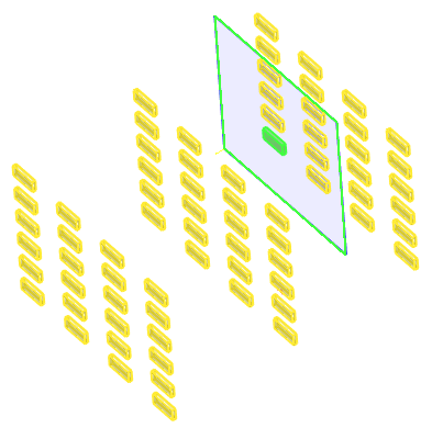
The flat square 3D profile is selected as the limiting element of the three-dimensional linear array
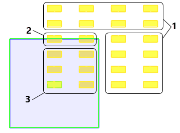
1 - Elements located fully outside the limitation scope (excluded from the array)
2 - Elements located partially outside the limitation scope (excluded from the array)
3 - Elements located fully inside the limitation scope (included in the array)
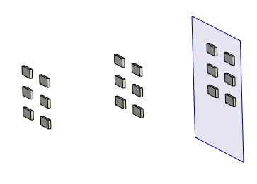
The operation result
If the limitation scope is defined by a flat 3D element, then the limitation axis coincides, by default, with the normal of the selected element's plane. If necessary, you can specify an arbitrary direction of the limitation axis by defining the axis directions by two 3D nodes or one 3D object suitable for defining a straight line.
In cases when the array limitation scope is described by a non-flat limiting element, the limitation axis must be explicitly specified.
In cases when the array limitation scope is described by a flat limiting element, the limitation axis must not be parallel to a plane of limiting element.
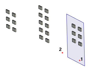
The same array as in previous pictures, but the limitation axis is defined by points 1 and 2.
The limitation scope can also be defined by multiple 3D elements. All elements are extruded in the same direction. The limitation scope will be the sum of extrusions of each limiting element.
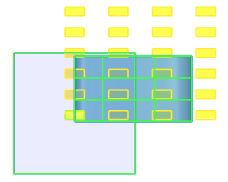
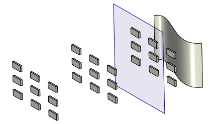
The non-flat limiting surface is selected in addition to the limiting profile
In cases when the array limitation scope is described by two flat limiting elements perpendicular to each other, the limitation axis must be explicitly specified.
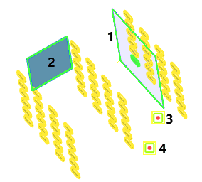
Two flat square 3D profiles (1 and 2) parallel to each other are selected as limiting elements.
The limitation axis is defined by points 3 and 4.
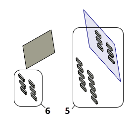
5 - Copies located inside the extrusion area of the first limiting profile.
6 - Copies located inside the extrusion area of the second limiting profile.
Main concepts of exclusions in arrays of 3D elements are described below. The interface is described in the Exclusions in 3D Arrays section.
Exclusions, or excluded elements are the array elements that shall not be included in the resulting array. Any array elements can be excluded, except the source object.
Exclusions can be defined for ![]() linear arrays,
linear arrays, ![]() circular arrays and
circular arrays and ![]() arrays by path.
arrays by path. ![]() Arrays by pattern inherit exclusions from a pattern.
Arrays by pattern inherit exclusions from a pattern.
An exclusion is specified by its position in the original array, that is, the column, the row, and the height in the array, at whose intersection this element is located. The dimension of the array in the first direction defines the number of rows, in the second - the number of columns, in the third - the number of heights.
Rows, columns and heights in arrays are numbered as follows:
- 0, 1, 2, …, N-1 – in the forward direction (N is the number of copies in a row/column/height in the forward direction)
- -1, -2, …, -M+1 – in the backward direction (M is the number of copies in a row/column/height in the backward direction).
Note that the column, row and height in which the source object of the array is located, have number 0. This is important when defining exclusions.
Instead of the number of particular rows/columns/heights, one can use descriptive characteristics defining their position in the original array:
•Starting - the row/column/height in which the source object of the array is located (the number 0);
•Last - the row/column/height, which is the last in the forward direction of array creation;
•Last in Opposite Direction - the row/column/height, which is the last in the backward direction of array creation;
This way of specifying exclusion locations is convenient for removing elements of the outer rows/columns/heights from the arrays of variable size, especially when the array dimensions are defined by the total length and the step, or the total length and the number of elements. Suppose, for example, that you need to exclude an element in a linear array of size 4x4x4, that is located at the intersection of the last row, the last column and the last height of the array (assuming that the copies are created in the forward direction only). One can simply specify the element at the intersection of the row number 4, column number 4 and height number 4 as the element to exclude. However, should the array grow (for example, to 5 rows, 5 columns and 5 heights), the excluded element will have the same exact coordinates 4;4;4 (the last element of rows columns and heights now has the 5;5;5 coordinates). Instead, to have specifically the last element of the array always excluded, the exclusion should specify the element at the intersection of "the last" row and "the last" column.
The source object of array is highlighted in green, the exclusion is highlighted in white The first direction (rows) is indicated by the blue arrow, second direction (columns) - orange, third direction (heights) - red. Positions of elements in the each direction is indicated by numbers of the same color as the directional arrow. |
|
|
|
The initial linear array |
The initial circular array |
|
|
The result of increasing the size of the array by one element in each direction, if the position of the excluded element was defined by numerical coordinates (2; 2; 2). |
|
|
|
The result of increasing the size of the array by one element in each direction, if the position of the excluded element was defined as Last in each direction. |
|
Upon selecting an excluded element it is possible to additionally exclude the whole row, column or height containing this particular element.
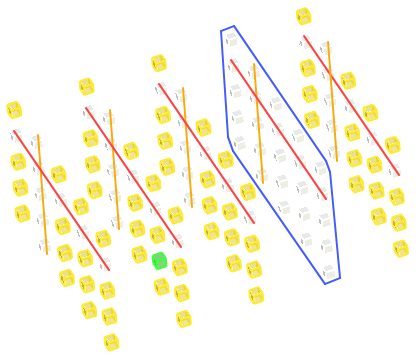
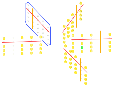
The result of excluding the second row (framed in blue), second column (strikethrough in orange) and second height (strikethrough in red) from arrays shown on the previous picture
•Cyclical Repeat. Enabling this option will cause deletion of not only the original exclusion, but also the elements following it after the same number of rows and columns from the start of the array. If this option is used together with the exclusion of rows/columns/heights, the whole rows/columns/height will be excluded in the same way.
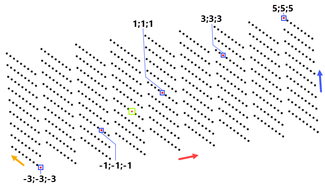
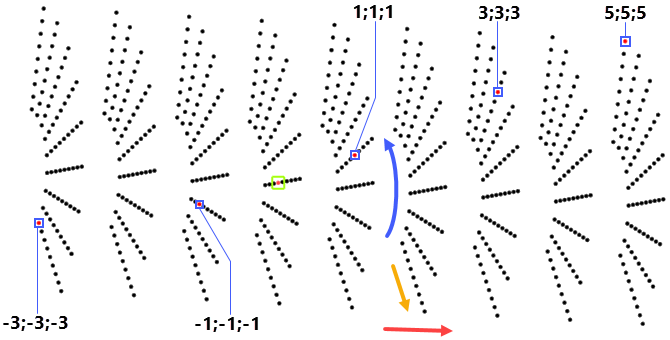
The result of applying the cyclical repeat to the element in position 1;1;1
in linear and circular three-dimensional arrays with 6 copies in each forward direction and 4 copies in each reverse direction.
First forward direction (rows) is indicated by the blue arrow, second (columns) - orange arrow, third (height) - red arrow.
Non-excluded elements are shown in black color.
The source object of the array is shown in red color and green frame.
Excluded elements are shown in red color and blue frame.
Numbers indicate positions of excluded elements.
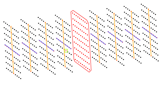
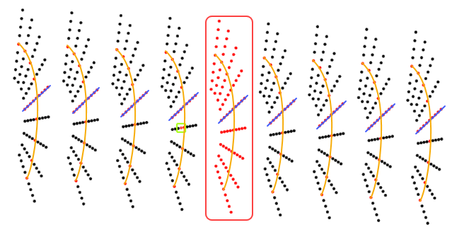
The result of excluding the row (strikethrough in blue),
the column (strikethrough in orange) and height (framed in red)
containing the element 1;1;1 from arrays shown on the previous picture
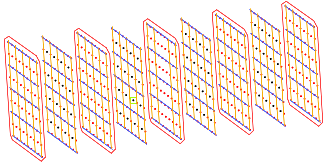
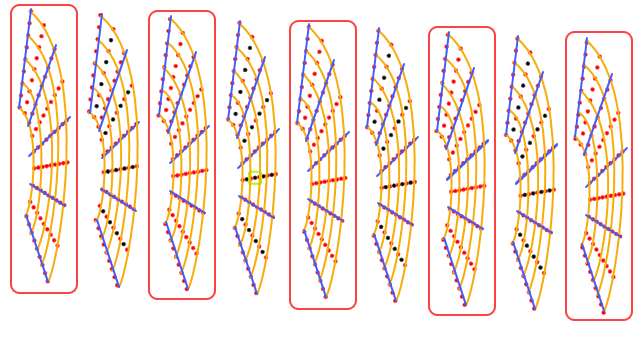
The result of applying the cyclical repeat to arrays shown on the previous picture
Topics in this section: