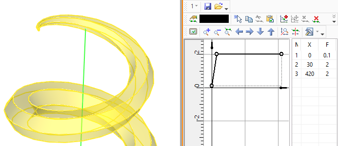
Main Concepts of Spiral along Axis |
  
|
The helical curve used for sweeping the profile is centered about the spiral axis. Axis can be either straight or curved.
Straight axis can be defined defined by two 3D points: the start point and the end point. 3D points can be defined by 3D nodes, as well as by any 3D objects suitable for defining a point in the space. The vector defining the spiral axis will be directed from the first point to the second one (this also defines the start and the end of the spiral, respectively). Alternatively, straight axis can be defined by point and direction or selected directly.
|
1 - First point of axis 2 - Second point of axis 3 - Spiral axis 4 - Screw curve 5 - Spiral profile |
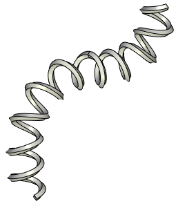
Curved axis can be defined by 3D paths, 3D profiles, loops, edges. Multiple selection is also acceptable if selected object form a tangency continuous contour. Contour could be either open or closed.
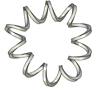
Selecting a closed axis yields a closed spiral by default.
There are limitations applied to constructing a closed spiral. Radius/diameter and profile scale should have same values in the end and in the start of the screw curve. X_tan parameter values in the starting and ending points of the pitch graph should be higher than zero.
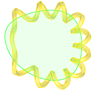
Closed spiral constructed using a pitch graph
Manually apply the desired length, if you need to create an open spiral by a closed axis. Limitations mentioned above are not applicable to open spiral created by closed axes.
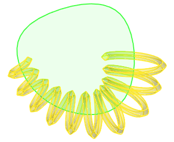
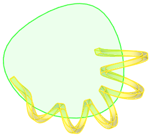
Screw curve of a spiral has following main parameters:
•Radius/diameter
A cylindrical spiral (i.e. the one with constant radius/diameter along the whole length) is created by default. It is possible to set different values for starting and ending radius/diameter. Then it will change linearly from start to end value along the helix length. Another option is to use graph of dependency between radius and length.
•Start angle and start point
Define the initial point of screw curve (see below).
•Direction of coiling
The clockwise direction (when looking along the spiral's axis) is applied by default. It can be switched to counterclockwise if necessary.
•Pitch, length and number of coils
The helix can be defined using one of the following parameters combination: Length and Coils, Length and Pitch, Pitch and Coils.
The third parameter is calculated automatically from the values of two others. By default, an axis's length is used as a spiral's length. It can be changed to a custom value if necessary.
When using the Length and Pitch combination, the pitch can be defined either by a constant value or by a graph in dependency to length.
|
|
Length of screw curve is defined by distance between 3D nodes that define axis (additionally, pitch is defined) |
Length of screw curve is defined by pitch value and number of coils (n=4) |
Initial point of spiral's screw curve
By default, the initial point of the screw curve is chosen arbitrarily by the system. It can be changed by setting the desired position using an additional 3D point - the start point. Additionally, you can specify the numerical value of the start angle of the screw curve's initial point rotation.
|
1 - Axis 2 - Default initial point of screw curve |
When you specify the start point, the initial point of the screw curve will move along the specified initial radius to the plane that passes through the selected point and the axis of the spiral.
|
1 - Selected start point 2 - Plane passing through axis and start point 3 - Initial point of screw curve |
When simultaneously setting the start point and the numerical value of the start angle, the angle is measured from the plane, passing through spiral's axis and the start point.
|
|
Initial point of screw curve is defined by numerical value of start angle (30°) without selecting start point |
Initial point of screw curve is defined by start point and numerical value of start angle (30°) |
Using start point for defining radius/diameter
Selecting a start point and disabling the start radius/diameter's checkbox links screw curve's radius/diameter to the start point's position.
|
Radius/diameter of screw curve is defined by start point |
Spiral profile and its orientation in the space
3D profile, 3D path, face, loop, edge or sequence of edges can be selected as a spiral profile. Selecting a closed contour results in creating a solid, selecting an open contour results in creating a surface.
|
|
Spiral based on closed profile |
Spiral based on open profile |
The profile position in the space is defined by a fixing vector. The spiral fixing vector is defined by two 3D points - starting and ending. If the profile is defined by 2D constructions, the profile fixing vector can be defined by two 2D points in the profile plane.
Once the spiral is created, the first point of the profile fixing vector is snapped to the end point of the radius vector at the spiral start. The direction of the fixing vector coincides with the radius vector.
|
1 - Radius-vector 2 - Spiral profile 3 - Original profile 4 - First fixing point 5 - Second fixing point 6 - Profile fixing vector |
After that, the profile is rotated about the fixing vector to achieve one of the following orientations: perpendicular to the screw curve, perpendicular to the axis or parallel to the axis.
|
|
|
Perpendicular to screw curve |
Perpendicular to spiral axis |
Parallel to spiral axis |
It is possible to flip the profile of the spiral about the radius vector by 180 degree.
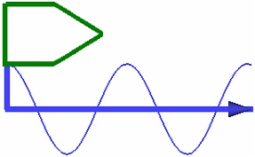
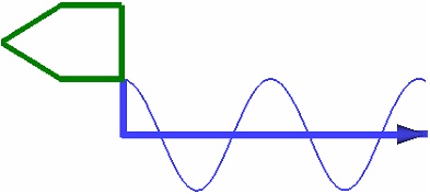
The selected profile is used in its original from by default. You can apply a Scale to it if necessary. Scale can be defined by a constant value or by a graph in dependency to the spiral length. For instance, using a scale graph allows to create a thread run-out representation.
Scale value should be higher than zero, otherwise the operation will throw an error.
