Spiral along Axis |
  
|
Spiral along Axis |
|
Spirals of this type can be created using the following option in the Spiral command:
|
Along Axis |

Following steps should be done to create a spiral along axis:
1. Choose axis type
2. Define spiral axis.
3. Define start point and/or start angle (optional).
4. Select profile.
5. Define profile fixing vector.
6. Choose profile orientation (optional).
7. Define profile scale (optional).
8. Define length, pitch, number and direction of coils of a screw curve (optional).
9. Define radius or diameter of a spiral (optional).
10. Confirm the operation ![]() .
.
Command parameters are described below.
For more information refer to the Main concepts of spiral along axis chapter.
Axis, Start Point, Start Angle

Following Axis Types are available:
•![]() Two Points
Two Points
•![]() Path
Path
•![]() Axis
Axis
•![]() Point and Direction
Point and Direction
Depending on the selected axis type, some of the following input boxes appear: First Point, Second Point, Path, Axis, Direction. Activating the desired input box allows to select in the 3D scene a corresponding object defining a spiral axis.
By default a spiral is constructed from start to end of an axis along the whole axis (or directional vector) length. However, it can be changed by specifying additional parameters.
The ![]() Reverse button is available for all axis types. It allows to switch spiral's direction along axis. For all axis types except
Reverse button is available for all axis types. It allows to switch spiral's direction along axis. For all axis types except ![]() Path this button switches between constructing a spiral from start to end of an axis and in reverse; the start itself is not changed in this cases. For
Path this button switches between constructing a spiral from start to end of an axis and in reverse; the start itself is not changed in this cases. For ![]() Path this button not only switches a direction, but also switches a start of a spiral between start and end points of an axis.
Path this button not only switches a direction, but also switches a start of a spiral between start and end points of an axis.
Start Point allows to manually define starting position of a spiral. If start point lays in axis's starting plane (a plane normal to axis, passing through its first point), then spiral's start lays on a line normal to spiral's axis going through start point. If start point doesn't lay in spiral's starting plane, the result depends on the ![]() For Angle Reference Only option. If
For Angle Reference Only option. If ![]() option is disabled (by default), then spiral's starting plane is shifted to the start point and after that spiral's start is defined in a way described above. If
option is disabled (by default), then spiral's starting plane is shifted to the start point and after that spiral's start is defined in a way described above. If ![]() option is enabled, then start point is projected to the starting plane. If start point is not selected, then the system automatically selects an arbitrary starting point.
option is enabled, then start point is projected to the starting plane. If start point is not selected, then the system automatically selects an arbitrary starting point.
If start radius or diameter is disabled, then radius/diameter of a spiral is defined by the start point.
Start Angle - an angle of a spiral start's rotation around a spiral's axis. If Start Point is selected, angle is laid off from said point, otherwise - from an arbitrary starting point automatically selected by the system.
Accuracy - object are being approximated or considered coinciding within this tolerance.

One of the following profile orientations can be selected in the Profile group of parameters:
•![]() Parallel to Axis
Parallel to Axis
The profile will remain parallel to axis along the whole spiral length.
•![]() Perpendicular to Axis
Perpendicular to Axis
The profile will remain perpendicular to axis along the whole spiral length.
•![]() Perpendicular to Path
Perpendicular to Path
The profile will remain perpendicular to screw curve along the whole spiral length.
Activate the Contour input box below to select objects defining a spiral profile in the 3D scene or in the model tree. The ![]() Reverse Profile button is located to the right side of the Contour input box. It flips the profile by 180 degree about a fixing vector
Reverse Profile button is located to the right side of the Contour input box. It flips the profile by 180 degree about a fixing vector
Upon selecting a contour, it is necessary to specify two points defining profile fixing vector. Starting point of the vector can be specified using the Fixing Point input box, ending point - using the X Axis input box.
The input box for defining a Scale of a profile is located below fixing points input boxes. Scale can be defined either by a constant value or by a graph depending on spiral's length along axis. To use a graph click the ![]() Create Graph button, which is located to the right side of parameter's input box. Detailed information is available in the Using Graphs in 3D Operations section.
Create Graph button, which is located to the right side of parameter's input box. Detailed information is available in the Using Graphs in 3D Operations section.

A combination of parameters defining a spiral's screw curve can be selected in the Parameters group. Following combinations are available:
•![]() Length and Coils (default)
Length and Coils (default)
•![]() Length and Pitch
Length and Pitch
•![]() Pitch and Coils
Pitch and Coils
Only two of three parameters (Length, Pitch and Coils) are available depending on the selected combination. Third parameter is calculated automatically from values of two others. For ![]() and
and ![]() options the Length is defined by axis length by default. Enable the checkbox located to the left side of the Length input box for applying a custom length value. All of the three parameters should have values higher than zero.
options the Length is defined by axis length by default. Enable the checkbox located to the left side of the Length input box for applying a custom length value. All of the three parameters should have values higher than zero.
When using the ![]() option, the pitch can be defined either by a constant value or by a graph depending on helix's length along axis. To use a graph click the
option, the pitch can be defined either by a constant value or by a graph depending on helix's length along axis. To use a graph click the ![]() Create Graph button, which is located to the right side of parameter's input box. Detailed information is available in the Using Graphs in 3D Operations section.
Create Graph button, which is located to the right side of parameter's input box. Detailed information is available in the Using Graphs in 3D Operations section.
Function value on the pitch's graph defines the number of coils for the corresponding length from the spiral's start.
Function on the pitch graph should be always increasing, otherwise the operation will throw an error.
The default spline graph contains almost horizontal starting and ending sections, where function value changes very slowly. This leads to creation of a spiral with starting and ending sections almost parallel to the axis.

Change spline's tangency parameters so, that function value change more rapidly, if you want to get rid of spiral sections parallel to axis. The spiral shown below is the same spiral as the one shown above; the only difference is the X_tan value for the first point of the graph.
The Direction of Coiling parameter as well as the ![]() Reverse Direction of Coiling button switch direction of spiral between clockwise and counterclockwise. The button is not pressed by default and the value is equal to zero. Pressing the button switches the value to one. Values can be also typed in manually or defined using variables. Only positive whole numbers are allowed. Values higher than one are considered same as one.
Reverse Direction of Coiling button switch direction of spiral between clockwise and counterclockwise. The button is not pressed by default and the value is equal to zero. Pressing the button switches the value to one. Values can be also typed in manually or defined using variables. Only positive whole numbers are allowed. Values higher than one are considered same as one.
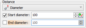
The Distance group of parameters allows to define change of spiral diameter/radius upon changing of coil number. First you need to choose one of following distance calculation options:
•![]() Radius
Radius
•![]() Diameter
Diameter
Either Start and End radius or Start and End Diameter input boxes become available depending on the selected option. Enable a checkbox located to the left side of a corresponding input box to apply a parameter. If Start Radius/Diameter is disabled, it is necessary to select a Start Point, so that spiral's radius/diameter will be defined by a start point's position. Then you will still be able to define the End Radius/Diameter if necessary.
If neither Start radius/diameter nor Start Point are defined, the operation throws an error.
By default, radius/diameter changes linearly from starting to ending value along the spiral's axis.
Alternatively, Radius/Diameter of a spiral can be defined by a graph depending on spiral's length along axis. This can be done by enabling only the Start Radius/Diameter checkbox and clicking the ![]() Create Graph button, which is located to the right side of parameter's input box. Detailed information is available in the Using Graphs in 3D Operations section.
Create Graph button, which is located to the right side of parameter's input box. Detailed information is available in the Using Graphs in 3D Operations section.
Start and end of a graph may expand beyond a spiral's length. The only limitation is that a graph should be defined along the whole spiral's length, otherwise the operation will throw an error.
On Polyline graph only two points are allowed - starting and ending. Otherwise the operation will throw an error

See also:
•Main Concepts of Spiral along Axis
•Using created body in Boolean operation