3D Node on Intersection of Elements |
  
|
3D Node on Intersection of Elements |
|
The command can be called in one of the following ways:
Icon |
Ribbon |
|
Support Geometry > 3D Node > 3D Node on Intersection of Elements |
Keyboard |
Textual Menu |
<3KNI> |
- |
Automenu of the |
|
<Q> |
On Intersection of Elements |
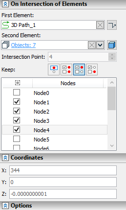
The command creates 3D nodes at intersections between a single 3D element and a set of 3D elements. The selection is performed via ![]() in 3D scene or in model tree. The first selected element is displayed in the First Element box in the On Intersection of Elements tab of the parameters window. You can
in 3D scene or in model tree. The first selected element is displayed in the First Element box in the On Intersection of Elements tab of the parameters window. You can ![]() Clear the selection using the button, which is located in the right side of the box. the list of other selected elements is displayed in the Second Element box in the same tab. You can Expand
Clear the selection using the button, which is located in the right side of the box. the list of other selected elements is displayed in the Second Element box in the same tab. You can Expand ![]() , Collapse
, Collapse ![]() , Clear
, Clear ![]() the list or Delete Element from the List
the list or Delete Element from the List ![]() using buttons located on the right side. Near the first and second element boxes there are icon indicating geometrical types of selected elements. During selection of elements, filters of geometry type prevent selection of elements, whose intersection is not a point. Thus, the first element should belong either to the
using buttons located on the right side. Near the first and second element boxes there are icon indicating geometrical types of selected elements. During selection of elements, filters of geometry type prevent selection of elements, whose intersection is not a point. Thus, the first element should belong either to the ![]() Axis or the
Axis or the ![]() Wire type, second elements - to
Wire type, second elements - to ![]() Axis,
Axis, ![]() Wire,
Wire, ![]() Geometric Surface,
Geometric Surface, ![]() Surface or
Surface or ![]() Solid type. All selected second elements should belong to the same type.
Solid type. All selected second elements should belong to the same type.
If there are several intersections between selected elements, the intersection, which was nearest to the point of clicking ![]() during the first selection of the second object, is selected by default.
during the first selection of the second object, is selected by default.
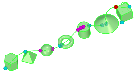
The Use Manipulators checkbox is enabled by default in the Options tab of the parameters window. In result, intersections are indicated by spherical manipulators in 3D window. The manipulator of the currently selected intersection is displayed in light red color, manipulators of other intersections - in light cyan. In order to select another intersection, move the cursor over its manipulator and press ![]() . Alternatively, you can switch between intersections by changing value in the Intersection Point input box, which is located below the list of second elements. This value defines the index number of the selected intersection. The value can be defined via a variable. Intersections numbering order depends on order of second elements selection and on proximity of intersection to the point of clicking
. Alternatively, you can switch between intersections by changing value in the Intersection Point input box, which is located below the list of second elements. This value defines the index number of the selected intersection. The value can be defined via a variable. Intersections numbering order depends on order of second elements selection and on proximity of intersection to the point of clicking ![]() during the selection of the second element, forming the particular intersection.
during the selection of the second element, forming the particular intersection.
Coordinates of the selected intersection are displayed in the Coordinates tab if the parameters window.


If there are several intersections, then the number and positions of created nodes depend on the state of the Keep parameters. It can be one of the following options:
![]() Current (default)
Current (default)
A node is created at the currently selected intersection only.
![]() All
All
Nodes are created at all intersections.
![]() Selected
Selected
When this option is selected, the list of intersections (nodes) is displayed at the bottom of the On Intersection of Elements tab of the parameters window. The nodes are created only at those intersections, whose checkboxes are enabled in the list.
![]() All Excluding Selected
All Excluding Selected
When this option is selected, the list of intersections (nodes) is displayed at the bottom of the On Intersection of Elements tab of the parameters window. The nodes are created only at those intersections, whose checkboxes are disabled in the list.
The names of the nodes in the list of intersections are based on index numbers of intersection. Names of nodes created in result of the operation might be different.
Checkboxes of intersections can be enabled and disabled either in the parameters window or in 3D window. Clicking ![]() a manipulator of intersection in 3D window switches the condition of intersections's checkbox in the list. Manipulators of intersections, whose checkboxes are enabled, are displayed in light magenta color. If manipulators are disabled, then selection and indication of intersections in 3D window is also disabled; so you can only see the preview of the currently selected intersection.
a manipulator of intersection in 3D window switches the condition of intersections's checkbox in the list. Manipulators of intersections, whose checkboxes are enabled, are displayed in light magenta color. If manipulators are disabled, then selection and indication of intersections in 3D window is also disabled; so you can only see the preview of the currently selected intersection.