Straight Construction Line through Node, Normal to Other Line |
  
|
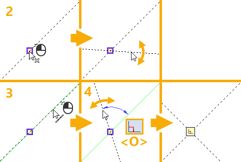
1. Call the ![]() Line command.
Line command.
2. Select a 2D node for the line to pass through. A node may be selected in one of the following ways:
•Move the cursor over the desired node, using object snappings, and press ![]() or <Enter>.
or <Enter>.
•Move the cursor over an intersection of construction lines or a characteristic point of a graphic line, using object snappings, and press ![]() or <Enter>. A connected 2D node will be created automatically at the specified point.
or <Enter>. A connected 2D node will be created automatically at the specified point.
•Activate the following automenu option:
|
<N> |
Select Node |
If the option is activated via keyboard, then the node nearest to cursor gets selected instantly.
If the option is activated via mouse, then you have to additionally press ![]() within drawing window for selecting the nearest node.
within drawing window for selecting the nearest node.
Upon selection, the preview of the resulting line will follow the cursor by rotating around the selected node.
3. Select a reference straight line for defining the angle. You can select a construction line or a graphic one. A line can be selected in one of the following ways:
•Move the cursor over the desired line, using object snappings, and press ![]() or <Enter>. In case of selecting a graphic line, a coinciding straight construction line is created automatically, and the current line is based on such construction line.
or <Enter>. In case of selecting a graphic line, a coinciding straight construction line is created automatically, and the current line is based on such construction line.
•Activate the following automenu option:
|
<L> |
Select related Line |
If the option is activated via keyboard, then the straight construction line nearest to cursor gets selected instantly.
If the option is activated via mouse, then you have to additionally press ![]() within drawing window for selecting the nearest line.
within drawing window for selecting the nearest line.
4. Activate the following automenu option:
|
<O> |
Create orthogonal Line |

The relation mark ![]() located at the intersection of the resulting line with the initial line indicates the perpendicularity.
located at the intersection of the resulting line with the initial line indicates the perpendicularity.
After creating a line, the command stays in the mode of creating ![]() arbitrarily angled lines and returns to the starting set of automenu options.
arbitrarily angled lines and returns to the starting set of automenu options.