Surface Curvature by Sections |
  
|
Calling the command
Icon |
Ribbon |
|---|---|
|
Measure> Geometry Analysis > Surface Curvature by Sections |
Keyboard |
Textual Menu |
<QF> |
Tools > Geometry Analysis > Surface Curvature by Sections |
This command allows you to create a section to display the curvature or curvature radius of one or more selected faces according to various options of the sections.
There are five section options.
|
By UV |
|
By Manipulator |
|
Radius |
|
Curves Flattening |
|
Parallel Planes |
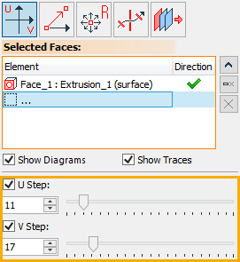
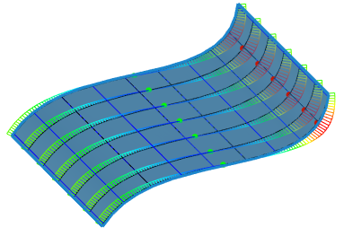
By UV option allows you to create a section to display the curvature or curvature radius of the selected faces by setting the step along U and V:
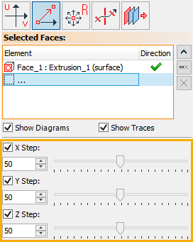
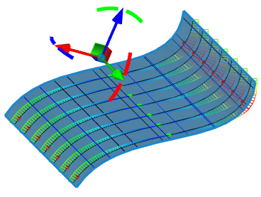
By Manipulator option allows you to create a section to display the curvature or curvature radius of the selected faces by setting the step along X, Y, Z or using the manipulator:
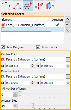
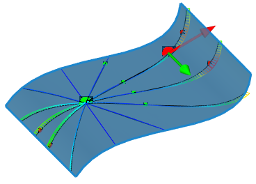
Radius option allows you to create a section to display the curvature or curvature radius using two points - the central point and the direction point, as well as specify the number of lines and the angular step.
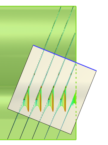
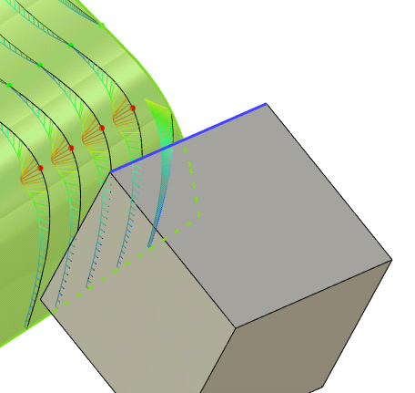
Curves Flattening option allows you to create a section to display the curvature or curvature radius using an additional edge of an individual body. To do this, you need to select the faces sequentially, and then the edges.
Parallel Planes option allows you to create a section to display the curvature or curvature radius by drawing planes parallel to different viewpoints. There are 5 modes for creating parallel planes - X, Y, Z, View, Plane.

In the case of choosing the X mode, a plane is created parallel to the X axis. In the case of choosing the Y and Z modes, planes are created parallel to the Y and Z axes.
View mode allows you to draw a plane parallel to the current point of view. For example, with a random point of view, the following section is provided on the cone:
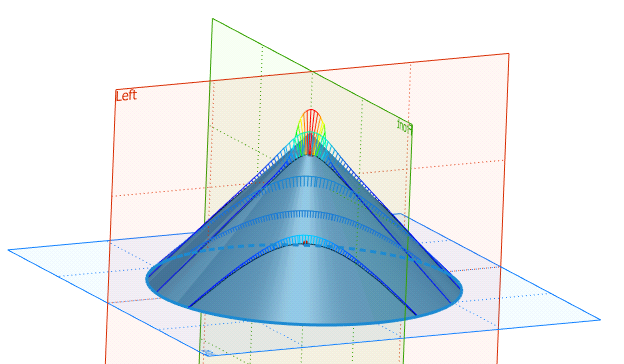
After creating a section and changing the point of view, the cone in the front view will look like this:
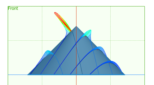
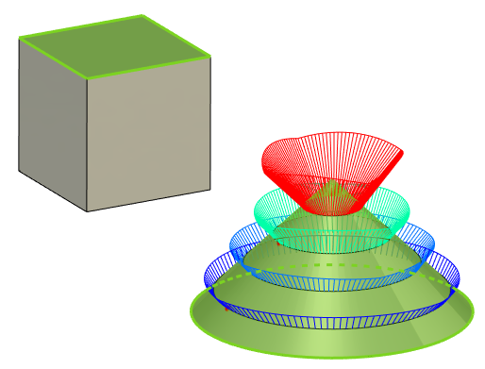
In the Plane mode, you must select the anchor plane, i.e. any plane without curvature.
Then, sections will be created from the selected plane with a certain step:
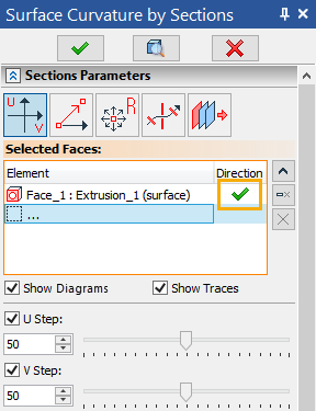
Using the Direction button, you can reverse the display of the curvature plot on the selected face.
For each section creation option, it is possible to disable the preliminary display of plots using the Show Diagrams option.
|
|
Option Show Diagrams is enabled |
Option Show Diagrams is disabled |
The Show Traces option enables traces of plots on selected faces:
|
|
Option Show Traces is disabled |
Option Show Traces is enabled |
It is possible to add a specific point for measurement. To do this, use the following option:
|
<P> |
Add Point on Face |
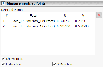
It allows you to add points on the face to the Measurements at Points field. You can remove the display of these points using the Show Points option, or leave only points in a certain direction (U or V).
To find the point of maximum curvature, use the option:
|
<M> |
Find point with maximal curvature |
When using this option, the system will automatically create a label indicating the point on the curve with the maximum curvature.
If you need to save the result of measuring the surface curvature of sections as a separate element of the model, you need to use the automenu option:
|
<R> |
Create Result |
The created measurement result will be displayed both in the model tree and in the scene.
It is possible to measure the curvature at a certain point. To do this, use the option:
|
<C> |
Measure curvature at arbitrary point |
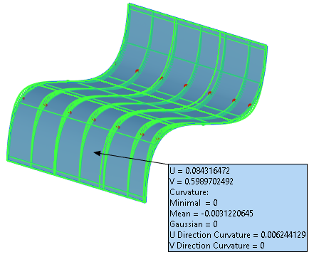
When you click anywhere on the curve, a label appears with the value of the curvature and the radius of curvature at this point. Such labels can be moved and they are saved using the Create Result option.
The Color tab works similarly to the Curve Curvature command.