3D Profiles |
  
|
3D Profiles |
|
A 3D profile is one of the most important elements in T-FLEX CAD. 3D profile is an oriented contour in the three-dimensional space. A 3D profile is oriented based on the orientation of the elements used for defining the profile (a workplane, worksurface, face or a set of edges).
A 3D profile can be created based on a parametric 2D contour located on a workplane page. This allows propagating parametric properties of two-dimensional drawings into the realm of solid modeling.
Sweeping a profile by any means in the space is the base operation for a solid body creation.
Main concepts. Types of profiles
Profile geometry
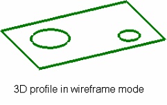
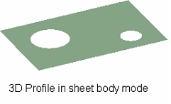
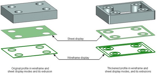
In a general case, a 3D profile is a sheet geometry element. For working convenience, profiles in the 3D scene are usually rendered as a wireframe, that this is a set of bounding lines (contours). However, one can set the 3D profile display mode is a sheet body.
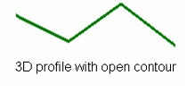
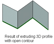
The contour of a 3D profile can be open. Such a profile will appear and behave as a wireframe geometry body in either display mode. For example, extruding such a profile will result in a sheet body, rather then a solid body as usual.
A 3D profile might contain several contours (bounding lines).
Types of profiles
All 3D profiles can be divided into five groups by the ways of their creation:
1. Profiles created based on 2D elements – hatches.
2. Profiles created based on 2D elements – text.
3. Profiles created based on 2D elements – graphic lines.
The above listed types of profiles can be created by the user explicitly, using a dedicated command, or created automatically by a system while managing the active workplane. These profiles are used at the initial stage of a solid body creation. As the body is being built by various operations, new surfaces, faces and edges are created, that can be used for subsequent operations. These elements can be used as a base for creating profiles of other types:
4. Profiles created based on solid body elements – loops (a closed chain of edges) or faces.
5. Profiles created by using existing profiles. For example, one can copy profiles or create offset profiles. One can also project or lay an existing profile on a three-dimensional solid body or on some of its faces.
6. Profiles created by unfolding a surface or a set of surfaces.
Profiles based on 2D elements
3D profiles created from the elements of 2D drawings are widely used in creation of 3D models. To create a profile, one can use hatches, text and graphic entities located on workplane and worksurface pages. When using a 2D element lying on a workplane page, the resulting 3D profile will be flat. A 3D profile created from a 2D element on a workplane will repeat the shape of the underlying surface.
Profiles based on hatches
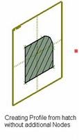
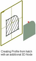
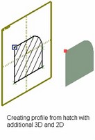
When creating a hatch-based 3D profile, its plane (surface) coincides with the workplane or a surface, whose page contains the original hatch.
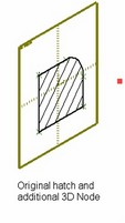
A flat 3D profile (based on a hatch on a workplane) can be repositioned in space. This can be done by using a 3D node through which the plane of the profile being created should pass. If that is not sufficient, one can refine the position of the 3D profile in space by specifying a 2D node (on the workplane containing the hatch), to which the selected 3D node should be snapped.
To create a 3D profile, one can use any hatches, including the ones created for decorating a 2D drawing. Those can be of any type: hatches, fills, outlining or hidden. However, the hatches created for a 2D drawing, are not always suitable for creating a profile of the required shape. In this case, one has to create a special hatch for the 3D profile. If such hatch is not necessary on the 2D drawing, we recommend using the "Invisible" type or put such elements on a special layer.
Note that one workplane (or, rather, its page) might contain several hatches, any of which can be used for creating 3D profiles.
Self-intersecting contours
Use of self-intersecting hatch contours is not allowed for creating a 3D profile. For example, if a hatch consists of two contours, then the situation shown on the left-hand side diagram is correct. The right hand side diagram shows a situation that leads to creating an erroneous contour.
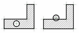
Initially, a 3D profile could be created based on a correct hatch contour. However, after a later editing of 2D construction elements, an erroneous situation may occur, which is the self-intersecting contour. In this case, an error message is output in the diagnostics window, and the 3D profile regeneration suspends until after the problem is fixed.
This rule (about prohibiting self-intersection of elements of a 2D contour used for creating the 3D profile) is applied not only to the profiles created from hatches. Self-intersections should be avoided also when using text (some TrueType fonts create self-intersections in certain letter combinations), and graphic lines.
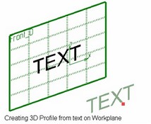
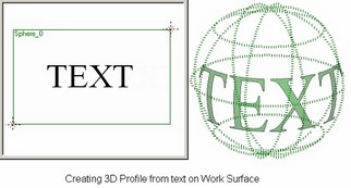
Profiles based on text
3D profiles based on 2D text are created identical to those based on hatches. Additional nodes may be specified for positioning a flat profile in the space. However, there is a limitation when creating text-based 3D profiles. Only TrueType fonts are supported.
The text in this case is considered a union of closed contours, where each contour is a separate character. Thus, the resulting 3D profile is a multi-contour one.
If elements are encountered in a text that cannot be transformed into the profile contour lines, these are ignored. For example, if a roughness symbol was inserted in a text, then only letters and numbers in the roughness notation will be used for generating the contour lines, while the strokes of the roughness symbol itself will be ignored.
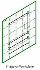
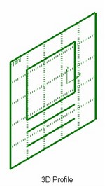
Profiles based on graphic lines on workplane
A 3D profile can be created based on all graphic lines lying on the specified workplane. The involved lines may constitute any image. This can be a connected sequence making a closed or open contour, or simply a set of separate lines. The graphic lines are even allowed to intersect. However, in this case one will have to use the thickening option for the profile being created (see the section "Thickening flat profile").
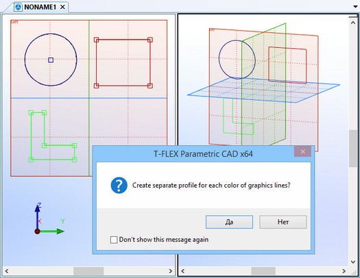
If all graphic lines on the workplane have the same color, then only one 3D profile is always created. To create several profiles, the graphic lines of different colors can be used. When creating a profile, the system will prompt the user to create a separate 3D profile for each color of the graphic lines. Upon approval, the number of the 3D profiles that will be created will be the same as the number of the colors that were used in creating the image on the workplane. By default, each 3D profile will be assigned the same color as the original graphic line.
In parameters of each 3D profile that was created by graphic lines, the lines whose color served as a basis for the creation of the given profile will be marked. If desired, the user can modify the color of the original lines later or altogether refuse the filtering of lines by color. In the latter case, the profile will be reconstructed by all graphic lines of the given plane.
If the image on the workplane is later modified (for example, new graphic lines added or existing ones deleted), the 3D profiles created based on this image will adjust accordingly.
Automatic creation of profiles from 2D elements (on active workplane)
A 3D profile can be created by the system automatically at the end of a session on the active workplane. In this case, the workplane must contain at least one 2D element of any of the following types:
● Hatch;
● A graphic line created by the command "SK: Create Sketch" or "G: Create Graphic Line" (the lines of 2D projections are not considered in this case);
● Text (using a TrueType font).
The 3D profile creation algorithm depends on the type of 2D elements present in the workplane. In the case when only graphic lines are present on the workplane, the system automatically creates a single new profile (the single-contour or multi-contour one). When later adding new graphic lines, the system will automatically add contours to the existing profile. If the identified graphic lines intersect, then use the thickening option for creating a 3D profile.
When several different types of elements are present in the active workplane, all suitable for creating a profile, then the system works differently. The graphic lines are ignored in this case. The profiles based on hatches and text only will be created at the end of the active workplane session. A separate profile will be created for each hatch and each text. Only if no 3D profile could be created from any hatches or text in the workplane, the graphic line-based profile will be created.
Profiles based on 3D elements – Loops, Edges, 3D profiles
Profiles based on loops or faces
This type of a 3D profile is created based on a loop (a closed chain of edges) or face (set of faces) of the 3D solid body. The geometry of this kind of profile is fully defined by the selected elements of the 3D body and adjusts to the body geometry modifications. In a general case, this type of profile may not be flat.
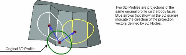
Projecting profile on face or body
A 3D profile can be created as a projection of another existing 3D profile on all faces of a 3D body or on its single face. In the case of projecting on all faces, the body itself is selected, when projecting on a face – a specific face. In this case, remember the following restriction: the projection of the selected profile should fully fit within the selected surfaces.
The projection vector of the original profile is defined either by one 3D object, capable of defining the vector (straight path or edge, LCS), or with the help of two 3D points (3D nodes, vertices of bodies, etc.). If the projection vector is not defined, then the projection is constructed along the normal to the selected face. Selecting the body is equivalent to selecting a set of faces. Therefore, in this case the projection vector will be defined as the normal to the nearest face.
Copying 3D profile
To create a 3D profile as a copy of an existing profile, simply select the original 3D profile. The thus created profile will coincide in space with the original profile. Various transformations defined among the profile parameters will be applied with respect to the world coordinate system.
If necessary, one can additionally specify the original and the target coordinate systems. In this case, profile copying translates the profile from the original to the target coordinate system. The transformation parameters defined for the profile will be applied with respect to the original coordinate system in this case.
The capability of copying 3D profiles relieves the user from creating additional workplanes.
3D offset profile
3D offset profiles can be constructed from flat 3D profiles only. The original profile can be a multi-contour one. To create an offset profile, select the original profile and specify the offset with respect to the original profile. Offsets can be defined in two ways: By defining a 3D node for the offset to pass through. The node should lie in the plane of the original profile. By a numerical amount of the offset distance for the target profile from the original profile. The diagram shows an example of creating an offset profile at a negative distance.
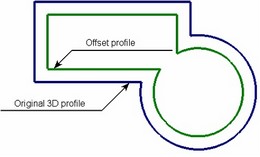
This drawing is located in the folder "Examples \3D Modeling\Profile\Offset Curve.GRB".
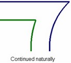
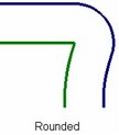
When creating an offset, three ways of handling gaps between the offset strokes are possible:
●Natural – the curves that make the original contour are continued naturally. Straight lines are continued straight, arcs - round.
●Round – rounds are constructed between the ends of the neighboring strokes of the contour being created.
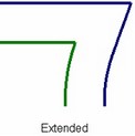
●Extend – the gaps are closed by straight lines tangent to the strokes at their ends.
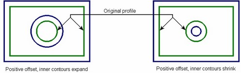
If the original profile to offset from contains inner loops, their handling will be defined separately, regardless of the offset distance sign. One of the two options can be chosen:
●Enlarge – offsets to inner contours are constructed by expanding the original contours, regardless of the offset distance sign.
●Decrease – offsets to inner contours are constructed by shrinking the original contours.
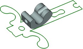
Laying profile on face or body
This functionality allows creating a new profile by laying the original flat profile on a face or set of faces in the body. How does it work? A point is selected in the profile plane to be tied to a point in the face. The point selected on the profile is projected on the selected point on the face. After that, the profile is wrapped around the face, as if a paper label on the bottle. One can use additional elements for precise profile positioning. The reference point in the profile plane used for projecting on the surface is defined by a 3D node lying on the original profile. The area for the profile to be laid on can be represented either by a separate body face or by a set of adjoining faces.
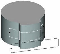
The profile transformation is performed without rips or shrinkages of its surface –the area of the original and the resulting profiles is the same. This condition poses restrictions on the used faces or sets of faces.
The faces allowed for laying profile are those that can be created by simple extruding. However, those don't have to be produced by the extrusion operation per se. For example, a cylinder is allowed, since it can be created by simple extruding, even if it was actually created by the rotation. On the other hand, a cone, sphere or torus is not allowed, since it cannot be created by the simple extrusion.
The point on the face used for tying the original profile is defined by a 3D node. The profile is tied to the first selected point (the first point selected on the profile is snapped to the point on the face).
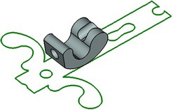
Then, a plane is constructed through the selected 3D node on the face orthogonal to all used faces. If the selected faces were constructed by an extrusion, then this plane would have been orthogonal to the extrusion direction. The profile will be laid along the intersection line between this plane and the selected faces. At this point, two possibilities exist for defining the direction of the profile laying along the intersection line. The profile can be laid on either side of the reference point (see the diagram).
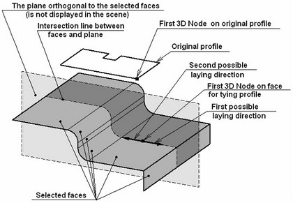
The plane orthogonal to the selected faces, the intersection line between the plane and the faces and the direction vector of laying the profile are not displayed in the scene. Those are shown in the diagrams for illustration purpose only.
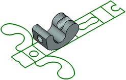
To define the direction of laying the profile uniquely, one can select the second point on the used faces. The selected node will define which out of the two possibilities should be used as the direction of laying the profile.
If the set of faces is defined in such a way, that the first point belongs to a side face, then the laying direction is determined automatically – towards the adjoining faces. This is the case when you do not have to select the second point on the face.
Both cases described above are illustrated by the following diagrams:
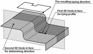
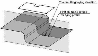
The diagram on the right hand side shows the case, when the first selected 3D node (on the surface) belongs to a side face. In this case, the laying direction is determined automatically.
Next, the profile orientation on the face needs to be resolved.
The vector that defines the profile orientation on the face (set of faces) can be defined in two ways: by using the second point on the profile plane, or without it. This vector is not displayed in the scene, and is shown in the diagrams for clarity.
When using the second point, the start and the end of the new vector will be defined by the first and second points on the profile plane. In the cases, when the second point on the profile plane is not selected, the direction is determined by the following algorithm:
- The laying direction vector beginning at the first point on the surface is projected on the profile plane. This gives the direction of the new vector for profile orientation.
- The start of the profile-orienting vector is placed in the first point on the profile plane.
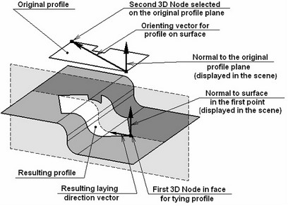
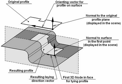
The arrows that are drawn from the first point on the profile and on the face show the normal directions to the profile plane and to the surface. When laying the profile, the profile plane is reoriented to have its normal coincide with the normal to the surface in the first selected point. The normal direction of the profile plane can be flipped to the opposite. This allows turning the laid profile 180° about the laying direction axis.
Profiles – unfoldings of a surface or a set of surfaces
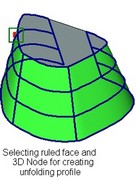
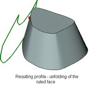
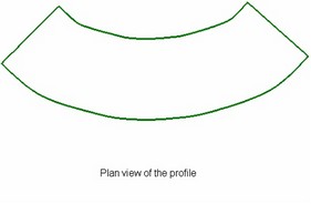
Constructing unfolding of ruled face
To construct a 3D profile as an unfolding of a ruled surface, select a face of the respective type. The face can be as either closed or open, with or without holes of various shapes.
The profile is constructed in the plane tangent to the surface of the original face. The tangency point of the profile or face can be specified by any 3D object which is capable of defining a point (for example, 3D node or vertex of the body). Specified point has to lie on the original face. If the selected face is closed (periodic), the same 3D point is used for defining the cutting line of the unfolding. The cutting line follows the generatrix line through the given node.
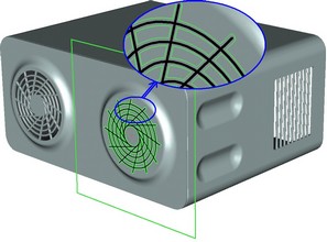
Creating unfolding of cylindrical face
To create a 3D profile as an unfolding of a cylindrical face, select the face to unfold and the tangency point for the plane of the face from which the unfolding profile is being created.
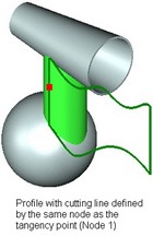
If the face is closed, the cutting line of the unfolding may pass along:
● The generatrix passing through the tangency point between the profile plane and the selected face surface.
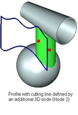
● The generatrix passing through an additional 3D point.
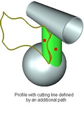
● A 3D path. The path must satisfy the following requirements:
- Lie in the same geometrical surface as the face being unfolded. (To achieve that, one can create an arbitrary 3D path first, and then project it on the face. One can also create a path in cylindrical coordinates with the same position and radius as the face being unfolded.)
- The ends of the path must lie on the end boundaries of the face.
The diagrams show an example of constructing a 3D profile as an unfolding of a closed cylindrical face, using all three types of face cutting for unfolding. Node 1 was used for defining the tangency point between the profiles and the original face, as well as for defining the cutting line for one of the profiles. The additional Node 2 and 3D path were used for defining the unfolding cutting line in two other cases.
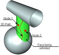
The resulting profiles lie in the same plane tangent to the surface of the original face at the point defined by Node 1, but differ in the cutting line.
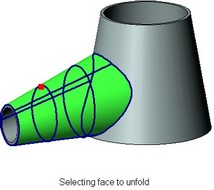
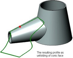
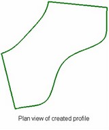
Creating unfolding of conic face
To create a profile as an unfolding of the conic face, select a conic face. Allowed for selection are faces whose extended surface makes an arbitrary round cone.
The profile being created is constructed in the plane tangent to the surface of the original face, just as in the case of creating other types of unfolding profiles. The tangency point can be specified by any 3D object, which is able to define a point (for example, 3D node or vertex of the body). Specified point has to lie on the original face. An additional 3D point can be defined for closed faces, to be used for defining the unfolding cutting line. The point defines the choice of the generatrix, along which to cut the unfolding of the face. If no additional point is specified, the unfolding is cut along the generatrix passing through the tangency point between the profile and the face.
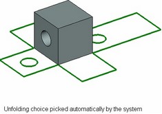
Creating unfolding of set of faces
Creating a 3D profile as an unfolding of a set of faces is mostly similar to creating other unfolding profiles.
To create such a profile, select the body faces to unfold. The selected faces must have common edges. When creating the profile, each face's surface is unfolded (if flat and unfoldable), and the set of faces is unfolded about common edges.
The position of the profile in space is defined by a 3D point on one of the selected faces. The plane of the profile will be tangent to that face at the specified point.
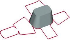
Several solutions could be possible when creating a profile. (An example is unfolding all faces of a cube.) By default, the system picks up a solution automatically. To make a specific choice of profile construction, one can additionally select "inseparably linked" edges that will be used as the unfolding lines. When specifying edges, one should define the links between all necessary faces. Otherwise, the faces will be ignored in the profile creation, for which "inseparably linked" edges are not defined that would connect those with other faces in the set.
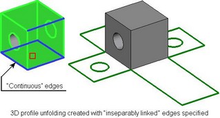
By default model edges will not be visible on the unfolded profile. However they can be created if necessary.
Thickening flat profiles
Any flat profile representation can be changed using Thickening mode. In this mode, the contour lines of the profile are offset. The new, thickened, contour is constructed based on these lines. The contour geometry may change in this case, which can be readily seen in the display of the sheet profile or the solid body resulting from it. When creating a 3D profile based on 2D elements, the use of this mode may become the only way of constructing the profile. This happens, for example, when the original graphic lines, hatch or text strokes used for constructing the profile have self-intersections or forks.
In this case, the system will not be able to create the profile, unless in this mode, and will automatically prompt the user for turning on the thickening mode.
Thickening of a 3D profile depends on the following parameters that affect the resulting shape:
- Thickness type (the direction(s) of offsetting the original contour lines);
- Offset distance (distances) from the original 3D profile contour lines;
- Ends handling of the new 3D profile contour lines;
- Gap handling between the hanging ends of the offset 3D profile contour lines;
- Closed area handling (specific to 3D profiles created from graphic lines on a workplane).
Gap handling and closed area handling work the same way as the respective parameters in the offset profile creation. The rest of parameters are described here.
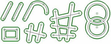
Note that different shapes of the original 3D profile contour lead to different behavior of this mode.
Thickening types and line offsetting
Offsets can be created at either or both sides of the original lines, at specified distances in each direction, equal or unequal. The offset distance is defined by a numerical value.
In theory, the way of constructing offsets is determined by the thickening type that allows the following choices:
● Outward, inward – the offset lines are constructed on one side of the original contour lines; for closed contours, the direction of offsetting with respect to the original lines is defined by the selected mode (that is, either by expanding or by shrinking the original contour); the offsetting direction for open contours is automatically picked by the system.
● Symmetric – the offset lines are constructed on both sides of the original contour lines at equal distances;
● Double sided – the offset lines are constructed on both sides of the original contour, at different distances.
Depending on the selected type of thickening, one or two Offset distances are required. One value is required for the first three choices of thickening ("outward", "inward", "Symmetric"), two – when the "Double sided" option is chosen.
In real life, however, the shape of offset lines is determined, besides the thickening type, by the shape of the original contour. It depends on the presence in the original contour of self-intersections or forks, as well as closed areas. For example, a contour with self-intersections or forks in most cases can't be thickened on two sides by different offset distances. Use of choices "Outward" or "Inward" is not allowed for such contours either. The result of subjecting it to the option "Double sided" will also depend on the presence of closed areas in the contour. This choice of thickening is also impossible if there aren't such areas in the original profile contour. To be precise, use of the option in this case will result in the same shape as the choice of "Symmetric", that is, the same offset distance will be maintained on either side of the original contour lines (the second offset distance being ignored). If the contour with self-intersections or forks contains closed areas, then the inward offsets (the ones created in closed loops) use one of the distances, while the outward ones (all the rest) use the other offset distance.
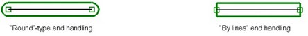
Handling ends of lines in thickened profiles
When thickening an open contour, the offsets from the hanging ends of lines can be joined by the following two ways:
●Round – the ends of the offset lines are joined by circular arcs.
●By line – the ends of the offset lines are joined by straight lines.
Creating a 3D profiles
To create any 3D profile, use the command "3PR: Construct 3D Profile". The command is called as:
Icon |
Ribbon |
|---|---|
|
3D Model → Construct → 3D Profile |
Keyboard |
Textual Menu |
<3PR> |
Construction >3D Profile |
To create a 3D profile, upon calling the command, select the required type of constructing the profile. The further steps depend on the selected type of the profile.
Creating 3D profile based on 2D hatch or text
Creating 3D profiles from graphic lines on workplane
Creating 3D profile based on loop or face
Creating profile -projection of existing profile on face or body
Creating 3D Profile - Copy of Existing 3D Profile
Creating a 3D profile - offset
Laying profile on face or body
Creating 3D profiles – surface unfoldings
Parameters of 3D profiles
As any other system element, each 3D profile has a set of parameters, which is the same for all types of profiles. The parameter values can be defined by calling the parameters dialog box via the option:
![]() <P> Set entity parameters
<P> Set entity parameters
The parameters dialog box of a 3D profile has three tabs: "General", "Thickness" and "Transformation". The tab "Thickness" contains the parameters that duplicate the contents of the same-name section of the property window provided with the profile creation command, as described above. The tabs "General" and "Transformation" are described in details in the chapter "Common parameters of 3D elements". We will mention here just the special parameters provided in the tab "General" specifically for 3D profiles:
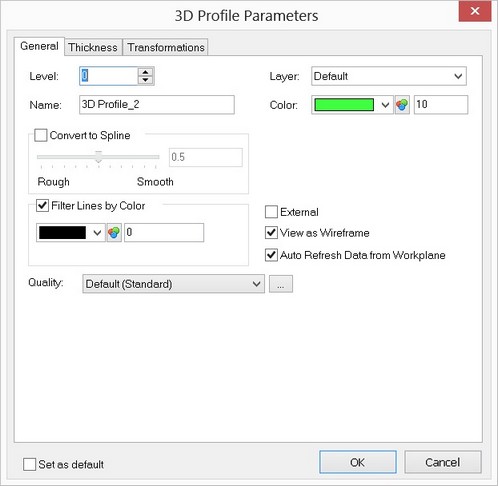
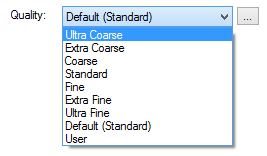
Quality. Parameter determining the quality of the image of a 3D profile. It defines the degree of model discretization into the grid of triangular planar faces for output of the image in 3D window. From the drop down list the predetermined sets of parameters specifying the quality of the grid can be selected:
●Extremely coarse; ●Coarse; ●Coarser; ●Normal; ●Finer; ●Fine; ●Extremely fine; |
|
|
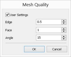
●From the status (Custom) – the values of parameters of model discretization are taken from the “ST: Set Document Parameters” command (the “Image quality” parameter on the “3D” tab); ●User-defined – the values of parameters of model discretization are specified by the user. Additional button[…] invokes the dialog window for specifying user-defined values of parameters of model discretization (in units of a model). In the dialog of mesh parameters it is possible to specify the user’s own values: allowance by edge, face precision and angular allowance. |
|
|
External. If the model is used as a 3D fragment, then the profiles with this parameter set are made accessible in the assembly mode. Those can be used for creating operations. The position of such a profile is fully determined by the position of its respective model. Only parameters can be modified. The profiles derived from 3D fragments have special names (Reference Profile No). These profiles can also be assigned the attribute External, that will allow their use in the assemblies of higher level.
Auto refresh data from Workplane. With this flag cleared, some changes in the work plane page will not be reflected in the 3D profile even after a full regeneration (such as, for instance, adding new contours made of graphic lines).
View as wireframe. This flag controls the way of rendering the profile in the 3D scene. If it is cleared, the profile is rendered as a sheet body. The flag is on by default, and the profile is displayed in the wireframe representation.
Convert to spline. This parameter allows converting each profile contour into a single spline. Each contour of the thus converted path or profile consists of a single segment, with the intermediate vertices being removed. The approximation accuracy is controlled by the parameter from 0.0 (Rough) to 1.0 (Precise) by the slider or via the accuracy input box, similar to the mesh density. In certain cases, such 3D profiles are more suitable then those based on polylines (as, for instance, in the "Loft" operation).
This parameter does not affect combination profiles, whose several faces have adjoining edges (for example, if the profile is created from a set of adjoining faces).