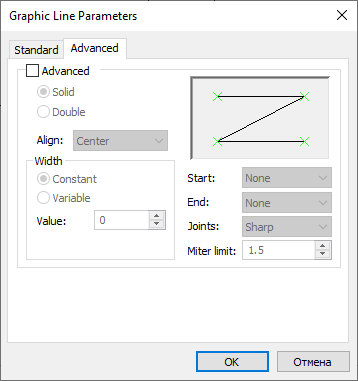
Advanced Parameters of Graphic Line |
  
|
The Advanced tab of the graphic line parameters dialog contains advanced parameters of line thickness described below. In order to set and apply them, you should enable the Advanced checkbox at the top of the tab. Upper right section of the tab contains the image of the Z-shaped line allowing to preview the result of applying the specified parameters.
Parameters specified in this tab are not applicable to lines based on custom line patterns.

You can switch between the following width application methods:
•Solid
The resulting line object will look like a single line, whose thickness is defined by Width parameters specified below. The Thickness parameter specified in the Standard tab is not applied in this case.
•Double
The resulting line object will look like two contour lines. Distance between these lines is defined by Width parameters specified below and thickness of these lines is defined by the Thickness parameter specified in the Standard tab.
The rest of parameters specified in the Standard tab is applied regardless of the parameters specified in the Advanced tab.
Align
The direction of Width parameters application.
•Center
The width is applied symmetrically in relation to the direction from starting to ending node of the line.
•Left
The width is applied to the left in relation to the direction from starting to ending node of the line.
•Right
The width is applied to the right in relation to the direction from starting to ending node of the line.
Width
Depending on the application method selected above, the width either defines the total width of the whole line, or the distance between its two contour lines.
You can switch between following types of width:
•Constant
The width is constant along the whole length of the line. The width value is specified in the Value box below.
•Variable
The width values are specified separately for the starting and ending node of the line in the On start and On end boxes below. Along the length of the line, the width changes uniformly from starting to ending value.
Start and End
The shape of the line at starting and ending node correspondingly.
•None
If the Double width application method is selected and the Width on start/on end is not equal to zero, then contour lines won't be connected to each other at starting/ending node, when using this option.
If the Solid width application method is selected, then this option will yield the same result, as the Square option.
•Square
The contour is limited by the straight segment passing through starting/ending node at normal angle to the bisector of the angle between contour lines.
•Round
The contour is limited by the circular arc centered at starting/ending node and tangent to contour lines.
Joints
The shape of the line at transitional nodes, where it forms angles (if the line contains such nodes).
This parameter is applicable only to lines created from 2D paths.
If an outer contour of an angle passes through the corresponding node, the angle has sharp shape regardless of this parameter. Otherwise, one of the following options is applied:
•Round
The outer contour of the angle is trimmed by the arc centered at the angular node and tangent to contour lines.
•Sharp
The outer contour of the angle is not trimmed.
•Mitered
The outer contour of the angle is trimmed by the straight segment passing at normal angle to the bisector at a distance from the angular node specified in the Miter limit box below. The distance is specified in relative units, where 1 corresponds to the distance between the angular node and the outer contour of the angle. If the value is ≤1, the angle is not trimmed.
See Also: