Edit Graphic Line |
  
|
Edit Graphic Line |
|
Editing graphic lines is done by the command Edit Graphic Line. Call the command via:
Icon |
Ribbon |
|---|---|
|
|
Keyboard |
Textual menu |
<EG> |
Edit > Drawings > Graphic Line |
The following options become available upon calling the command:
|
<*> |
Select All Elements |
|
<R> |
Select element from list |
|
<Esc> |
Exit command |
When in the command, one can select a graphic line entity by pointing the cursor and clicking ![]() .
.
All graphic lines can be selected at once by typing <*>. To add a graphic line to the set of already selected ones, use the combination <Shift> +![]() . To exclude a graphic line from the selected set, use <Ctrl>+
. To exclude a graphic line from the selected set, use <Ctrl>+![]() .
.
The following options become available after selecting one or several graphic lines:
|
<P> |
Change graphic line parameters |
|
<Alt>+<P> |
Copy Properties from Existing Element |
|
<I> |
|
|
<Del> |
Delete selected Element(s) |
|
<Esc> |
Cancel selection |
If only one graphic line is selected, then the following option is additionally available:
|
<O> |
Create Name for selected Element |
If a graphic arc entity is selected, the following additional options become available in the automenu:
|
<Tab> |
Change arc direction |
|
<A> |
Link Arc or Circle to Node |
|
<B> |
Break Link with Node |
If the selected graphic line is created based on a construction line, then Relations for the parent construction line will appear in the 2D window. Those relations are temporary, meaning that those are created by the system automatically upon entering the mode of editing a graphic line, and are automatically deleted upon exiting the mode. Using Relations, you can modify geometrical parameters of the parent construction line in the transparent mode.

Besides that, if the selected graphic line is created based on a construction line, then the second click ![]() after selecting the line (while the cursor is pointing at the line) will invoke the command of editing the original construction line.
after selecting the line (while the cursor is pointing at the line) will invoke the command of editing the original construction line.
Learn more about these options.
Option ![]() (<P>) allows you to change the parameters of the selected graphic lines. The parameters of the last selected image line are taken as the initial ones.
(<P>) allows you to change the parameters of the selected graphic lines. The parameters of the last selected image line are taken as the initial ones.
Changing the parameters of the graphic line in case of selecting one element is the same as setting the graphic line parameters.
If you have selected several image lines for editing, then you need to set the parameters for multiple editing, and then edit graphic line parameters directly.
To open the parameters dialog box for a single graphic line, one can simply double-click it (![]()
![]() ).
).
Option ![]() (<O>) allows you to assign a unique name to the selected graphic line that uniquely identifies this graphic line. Therefore, this option is available when only one graphic line is selected.
(<O>) allows you to assign a unique name to the selected graphic line that uniquely identifies this graphic line. Therefore, this option is available when only one graphic line is selected.
For graphic lines that have a name, you can get its length in the variable editor using the get() function - LENGTH. The get() function in the variable editor for a graphic line named NAME will look like this: get ("NAME", "LENGTH").
The option ![]() (<Z>) allows flipping the direction of graphic arc entity creation.
(<Z>) allows flipping the direction of graphic arc entity creation.

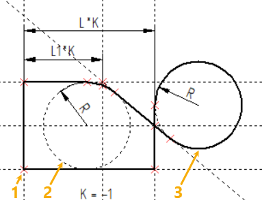
The following options are available in the automenu for graphic arc entities, ![]() and
and ![]() . These options manage a locking node of graphic arcs constructed on top of a construction entity. Throughout modifications of the drawing, the graphic arc will stay over the sector of the underlying construction circle that is closer to the locking node.
. These options manage a locking node of graphic arcs constructed on top of a construction entity. Throughout modifications of the drawing, the graphic arc will stay over the sector of the underlying construction circle that is closer to the locking node.
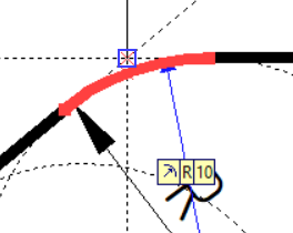
Let's review the following example. When moving one of the original lines, the part is supposed to get mirrored. However, the graphic arc will stay in its original orientation as the vertical line is moved, resulting in the wrong final shape of the part. This can be fixed by using a locking node.

To keep the arc always in the correct sector of the circle, link it to a node. After calling the command Edit Graphic Line select the arc and use the option ![]() . Then, select the locking node using
. Then, select the locking node using ![]() .
.
Now, as the vertical line is moved, the whole drawing will be flipping, maintaining the original relative configuration.
To release the link with the node, use the option ![]() .
.
Option ![]() (<I>) will allow you to deselect the last graphic line selection and select the next graphic line closest to the current cursor position. This option is used if there are two closely spaced graphic lines or overlapping graphic lines, and the wrong graphic line was selected on the first selection.
(<I>) will allow you to deselect the last graphic line selection and select the next graphic line closest to the current cursor position. This option is used if there are two closely spaced graphic lines or overlapping graphic lines, and the wrong graphic line was selected on the first selection.
Option ![]() (<Del>) deletes all selected graphic lines.
(<Del>) deletes all selected graphic lines.
Option ![]() (<Esc>) cancels the marking of the selected graphic lines.
(<Esc>) cancels the marking of the selected graphic lines.
It is possible to change the start and end nodes of the graphic line anchor. Changing the snap nodes becomes possible when you select one line of the image. After the line is selected, the nodes forming it are marked. You can move the cursor to the marked node and click ![]() . The cursor appears in the form of a rubber thread, showing the new position of the graphic line. You can select the node to which the graphic line should be anchored. After that, you need to move this line to the necessary location and click again
. The cursor appears in the form of a rubber thread, showing the new position of the graphic line. You can select the node to which the graphic line should be anchored. After that, you need to move this line to the necessary location and click again ![]() .
.
