Roughness in Drawing |
  
|
Upon calling the ![]() Roughness command, you should define the position of the roughness symbol in relation to the anchor point and the position of the anchor point in the drawing. Creation of a roughness designation without leader ends after defining the position of the anchor point. If you create a roughness designation with a leader, then after defining the position of the anchor point, you should additionally specify the position of the shoulder.
Roughness command, you should define the position of the roughness symbol in relation to the anchor point and the position of the anchor point in the drawing. Creation of a roughness designation without leader ends after defining the position of the anchor point. If you create a roughness designation with a leader, then after defining the position of the anchor point, you should additionally specify the position of the shoulder.
Position of a roughness symbol in relation to anchor point
Position of a roughness symbol in relation to anchor point depends on which of the following automenu options is selected:
|
<Alt>+<N> |
Roughness without Leader jog |
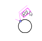
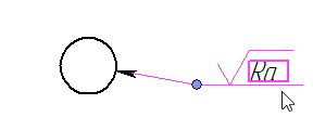
When using this option, the bottom point of the roughness symbol is its anchor point. The symbol is oriented along the snapping line in such way, that its top is located by the same side of the line as the cursor. If the orientation along the snapping line causes big counterclockwise angles of the symbol, then the symbol is placed horizontally on a shoulder of an automatically added leader. In such case the cursor position defines the position of the shoulder. The shoulder is connected to the snapping line by an arrow, which passes normally to the snapping line. The direction of such shoulder (to the left or to the right) is selected arbitrarily by the system and cannot be changed manually.
|
<Alt>+<L> |
Roughness with Leader jog |
When using this option, the roughness symbol is always placed horizontally on a shoulder (jog) of a leader. In such case, the anchor point only defines the tip of the leader's arrow. In order to define a position of the leader's shoulder, you have to additionally specify an arbitrary point via ![]() . Arrow of such leader can be placed at any angle in relation to the snapping line.
. Arrow of such leader can be placed at any angle in relation to the snapping line.
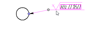
Initial direction of such shoulder (to the left or to the right) is selected arbitrarily by the system, but can be switched using the following automenu option:
|
<Z> |
Change leader line jog orientation |
|
<Alt>+<T> |
Attach to the sign point |
When using this option, the top right angle of the roughness symbol is its anchor point. The symbol is always placed horizontally without a leader.
Position of anchor point in drawing
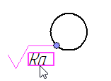
In order to define position of anchor point in a drawing, move the cursor over an object, which the roughness designation should be snapped to, and press ![]() or <Enter> with object snappings enabled. Position of the anchor point is displayed in the Coordinates tab of the parameters window. The method of defining the anchor point's position depends on the type of the snapped object. Roughness designation in drawing may be snapped to objects of the following types:
or <Enter> with object snappings enabled. Position of the anchor point is displayed in the Coordinates tab of the parameters window. The method of defining the anchor point's position depends on the type of the snapped object. Roughness designation in drawing may be snapped to objects of the following types:
•2D nodes;
•connections of graphic lines;
•intersections of construction lines, if there is at least one 2D node on each line;
•witness lines of linear dimensions;
•dimension lines of radial dimensions;
•straight construction lines, if there is at least one 2D node on a line;
•straight graphic line segments;
•circles and circular arcs (both graphic and construction ones).
When snapping a roughness designation without a leader to an arbitrary point or 2D node, the creation of the designation ends automatically right after specifying such point/node. When snapping to various lines, the preview of the roughness designation appears, upon selecting a line, and follows the cursor along such line. Set the desired position of the designation on the line by moving the cursor and confirm the input by pressing ![]() or <Enter>. As long as the position on the line is not confirmed, you may cancel the line selection by pressing
or <Enter>. As long as the position on the line is not confirmed, you may cancel the line selection by pressing ![]() anywhere within drawing window.
anywhere within drawing window.
You may also select objects of snapping using the following automenu options:
|
<N> |
Set relation with Node |
|
<L> |
Set relation with Line |
|
<C> |
Set relation with Circle |
|
<E> |
Set relation with Ellipse |
|
<S> |
Set relation with Spline |
|
<D> |
Set relation with Dimension |
|
<R> |
Set Relation with Leader Note |
Activate one of these options and click ![]() anywhere in a drawing. In result, the object of the corresponding type nearest to the point of clicking will be selected.
anywhere in a drawing. In result, the object of the corresponding type nearest to the point of clicking will be selected.
When snapping a roughness designation to an arbitrary point, its position is defined in absolute coordinates within the coordinate system of the active drawing view. Coordinates of the designation's anchor point are displayed at the Coordinates tab in the parameters window of the ![]() Roughness command.
Roughness command.
![]()
Enabling a checkbox located near the X or Y coordinate's name fixes such coordinate, so it no longer depends on cursor's position. Checkboxes are enabled automatically, when you type in coordinates using keyboard. You may also enable these checkboxes using <X> and <Y> hotkeys. Fixing of coordinates is indicated by a dashed blue line on a drawing: vertical for X coordinate, horizontal for Y.
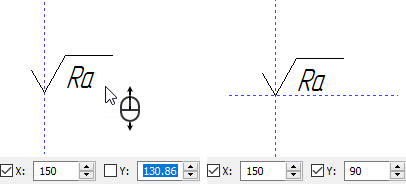
Coordinates of the anchor point can be inputted:
•Using the cursor
Simply place the cursor in the necessary position and click ![]() .
.
•Using the keyboard
Type in the X coordinate, then either press <Tab> or click ![]() the Y coordinate's input box, then type in the Y coordinate and click
the Y coordinate's input box, then type in the Y coordinate and click ![]() at any position within the drawing window.
at any position within the drawing window.
•Using the combination of aforementioned methods
Type in one of the coordinates first, then define the second one using the cursor.
After defining the coordinates, the creation of the roughness designation ends.
Upon calling the ![]() Roughness command, select a 2D node by clicking it with
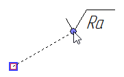
Roughness command, select a 2D node by clicking it with ![]() with object snappings enabled. In result, the roughness designation will be instantly created at the selected node. Instead of an existing 2D node, you may select a connection of graphic lines or an intersection of construction lines (if there is at least one 2D node exists on each of the construction lines). Then a 2D node will be created automatically at the selected point, and the roughness designation will be snapped to such node.
with object snappings enabled. In result, the roughness designation will be instantly created at the selected node. Instead of an existing 2D node, you may select a connection of graphic lines or an intersection of construction lines (if there is at least one 2D node exists on each of the construction lines). Then a 2D node will be created automatically at the selected point, and the roughness designation will be snapped to such node.
You may define offsets from the node later, when editing the roughness designation. The following automenu option is available during editing of a roughness designation snapped to a 2D node:
|
<F> |
Link to Node |
As long as this option is active, the anchor point of the roughness designation coincides with the snapped 2D node. If you disable it, then the anchor point will follow the cursor in all directions. The offsets between the anchor point and the node will be displayed in the Coordinates tab of the parameters window: dx - offset by the X axis, dy - offset by the Y axis of the active view's coordinate system. Same as when defining absolute coordinates, the offsets might be fixated by enabling the adjacent checkboxes via the mouse or the <X> and <Y> hotkeys. When using the anchor point's manipulator, the Link to Node option gets disabled automatically. Set the desired offset values in one of the ways described above. The editing of the roughness designation will end.
![]()
Snapping to straight lines using absolute offset
Upon calling the ![]() Roughness command, select a desired line by clicking it with
Roughness command, select a desired line by clicking it with ![]() with object snappings enabled. In result, the preview of the roughness designation appears and follows the cursor along the selected line. The Offset between the roughness designation's anchor point and some point on the selected line is displayed in the Coordinates tab of the parameters window:
with object snappings enabled. In result, the preview of the roughness designation appears and follows the cursor along the selected line. The Offset between the roughness designation's anchor point and some point on the selected line is displayed in the Coordinates tab of the parameters window:
•upon selecting a witness line of a linear dimension, the offset is measured from the intersection of the selected witness line with dimension line;
•upon selecting a dimension line of a radial dimension, the offset is measured from the intersection of such line with its source circle or arc nearest to the dimension value;
•upon selecting a main arrow of a leader note, the offset is measured from the tip of the arrow;
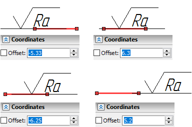
•upon selecting a straight construction line, the offset is measured from the nearest 2D node laying on the selected line; the nearest node is defined by the system automatically at the moment of selecting the line and it doesn't depend on further movements of the cursor;
•upon selecting a straight graphic line segment, the offset is measured from the nearest endpoint of the segment; the nearest endpoint is defined automatically by the system depending on the current position of the cursor and may be switched upon further cursor movements.
The offset is measured in absolute length units. Same as coordinates, the offset value may be fixated by enabling the adjacent checkbox via the mouse or the <Q> hotkey. Set the desired offset value in one of the ways described above. The creation of the roughness designation will end.
Snapping to curves using relative offset
Upon calling the ![]() Roughness command, select a desired curve by clicking it with
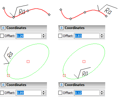
Roughness command, select a desired curve by clicking it with ![]() with object snappings enabled. In result, the preview of the roughness designation appears and follows the cursor along the selected line. The Offset between the roughness designation's anchor point and the starting point of the selected line is displayed in the Coordinates tab of the parameters window. For closed curves the starting point is arbitrary and coincides with the ending point. The offset value is measured in portions of the curve's length and may vary from 0 (starting point) to 1 (ending point). Unlike absolute offset, when defining the relative offset, the anchor point of the roughness designation cannot be placed outside the limits of the selected curve. Same as coordinates, the offset value may be fixated by enabling the adjacent checkbox via the mouse or the <Q> hotkey. Set the desired offset value in one of the ways described above. The creation of the roughness designation will end.
with object snappings enabled. In result, the preview of the roughness designation appears and follows the cursor along the selected line. The Offset between the roughness designation's anchor point and the starting point of the selected line is displayed in the Coordinates tab of the parameters window. For closed curves the starting point is arbitrary and coincides with the ending point. The offset value is measured in portions of the curve's length and may vary from 0 (starting point) to 1 (ending point). Unlike absolute offset, when defining the relative offset, the anchor point of the roughness designation cannot be placed outside the limits of the selected curve. Same as coordinates, the offset value may be fixated by enabling the adjacent checkbox via the mouse or the <Q> hotkey. Set the desired offset value in one of the ways described above. The creation of the roughness designation will end.
Snapping to circles and circular arcs
Upon calling the ![]() Roughness command, select a desired circle or circular arc by clicking it with
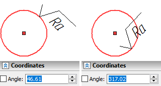
Roughness command, select a desired circle or circular arc by clicking it with ![]() with object snappings enabled. In result, the preview of the roughness designation appears and follows the cursor along the selected circle or along the circle forming the selected arc. The Angle, which defines the position of the roughness designation's anchor point on the circle, is displayed in the Coordinates tab of the parameters window. Zero angle corresponds to the point of intersection between the circle and its radius directed horizontally to the right. The angle is measured counterclockwise. Same as coordinates, the angle value may be fixated by enabling the adjacent checkbox via the mouse or the <A> hotkey. Set the desired angle value in one of the ways described above. The creation of the roughness designation will end.
with object snappings enabled. In result, the preview of the roughness designation appears and follows the cursor along the selected circle or along the circle forming the selected arc. The Angle, which defines the position of the roughness designation's anchor point on the circle, is displayed in the Coordinates tab of the parameters window. Zero angle corresponds to the point of intersection between the circle and its radius directed horizontally to the right. The angle is measured counterclockwise. Same as coordinates, the angle value may be fixated by enabling the adjacent checkbox via the mouse or the <A> hotkey. Set the desired angle value in one of the ways described above. The creation of the roughness designation will end.
