Roughness in 3D Scene |
  
|
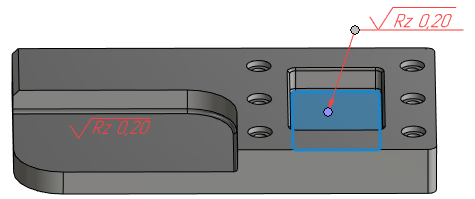
Roughness designation may be created not only in drawings, but also in the 3D space of 3D scene. 3D roughness designation may be used for creating corresponding 2D roughness designation manually or automatically, or as a source of information, when designing products without creating drawings.
Creating a roughness designation in 3D scene
Upon calling the ![]() Roughness command select the desired object, which the designation will be snapped to, by clicking it with
Roughness command select the desired object, which the designation will be snapped to, by clicking it with ![]() . In the T-FLEX CAD you can snap roughness designations in 3D scene to faces, edges, vertices and 3D paths. Upon selecting the object of snapping, the preview of the roughness designation appears.
. In the T-FLEX CAD you can snap roughness designations in 3D scene to faces, edges, vertices and 3D paths. Upon selecting the object of snapping, the preview of the roughness designation appears.
Wrong selection may be canceled by pressing ![]() anywhere within 3D window, or using the following automenu option:
anywhere within 3D window, or using the following automenu option:
|
<K> |
Break relations |
Position of roughness symbol in relation to the object of snapping depends on which of the following options is selected:
|
<Alt>+<N> |
Roughness without Leader jog |
If this option is selected, then the roughness designation is attached directly to the object of snapping and touches it by the bottom point of the symbol.
|
<Alt>+<L> |
Roughness with Leader jog |
If this option is selected, then the roughness symbol is placed on a leader, and a leader's arrow touches the object of snapping. In such case, the object of snapping only defines the position of the arrow. In order to define the position of the symbol itself, you have to additionally specify an arbitrary point within the 3D space by clicking it with![]() .
.

The exact point on the object of snapping, where the designation will be attached to, is defined by the position of the cursor at the moment of selecting the object.
When creating a roughness designation with leader, the shoulder (jog) of the leader always stays horizontal and adapts to the orientation of active camera. The initial direction of the shoulder (to the left or to the right of the arrow) is selected arbitrarily by the system. If necessary, you can switch it using the following automenu option:
|
<Z> |
Change leader line jog orientation |
Parameters of a roughness designation can be set in the parameters window at any stage of its creation. 3D roughness has the same set of parameters, as 2D roughness has, except the coordinates. When creating a 3D roughness, in addition to the options described in the current section, the automenu of the Roughness command contains common options of 2D elements creation commands
After selecting an object of snapping and specifying desired parameters, you have to finish the creation of roughness designation by pressing ![]() anywhere within 3D window, or by using the following automenu option:
anywhere within 3D window, or by using the following automenu option:
|
<Ctrl>+<Enter> |
Finish input |
Plane of roughness designation
Initially a roughness designation lays in a plane arbitrarily selected by the system. When editing the designation, you can manually select another plane using the following automenu option:
|
<T> |
Select Plane |
Upon activating this option, select a flat face or a workplane by clicking it with ![]() . If the selected plane doesn't pass through the snapping point of the roughness designation, then the designation will lay in a plane passing through such point parallel to the selected plane.
. If the selected plane doesn't pass through the snapping point of the roughness designation, then the designation will lay in a plane passing through such point parallel to the selected plane.
Link between 3D and 2D roughness
When you create a roughness in a drawing snapped to a 2D projection of a 3D feature, which a 3D roughness is snapped to, the parameters of such 2D roughness is inherited from the 3D roughness. Inherited parameters include the height, step, relative length, symbol, texture direction, and text strings before, after and above the symbol.
For roughness data inheritance you should update the 2D projection after 3D roughness creation before creating a corresponding 2D roughness. Data is only inherited by new roughness designations. If a 2D roughness designation was created before creation of a corresponding 3D roughness, the data won't be inherited.
Projecting 3D Roughness designations
After creating 3D roughness designations and other 3D annotations, you can automatically create corresponding 2D detailing elements, using the ![]() Create 2D Annotations command available in the contextual menu of 2D projection. See more in the Projecting 3D Annotations section
Create 2D Annotations command available in the contextual menu of 2D projection. See more in the Projecting 3D Annotations section