Drawing Detailing Elements on 2D Projection |
  
|
To design a drawing created on the basis of a 2D projection, you can use the standard drawing detailing commands - Dimension, Leader Notes, Roughness etc. This requires activation of the projection. When the projection is active, it is automatically ensured that it is impossible to set dimensions and other symbols attached to different projections.
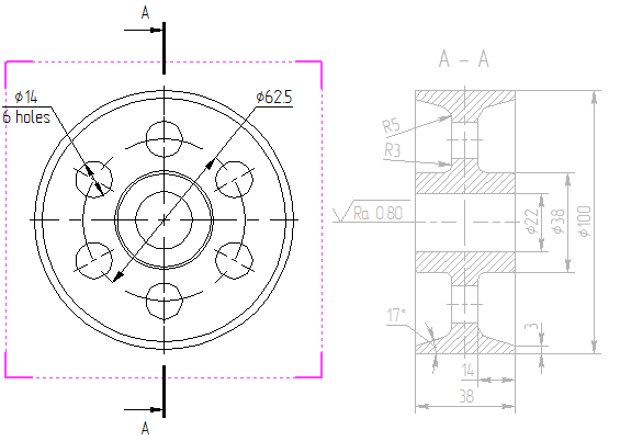
All dimensions specified on the projection page are attached to it, and when it is moved, they move with it.
With a significant change in the 3D model and recalculation of 2D projections based on it, the composition of the projection lines and the identification of some elements can sometimes partially change. In this case, some of the design elements created on the lines of 2D projections may lose their connection with the original elements. The system will notify about this by displaying messages in the diagnostic window.
The 3D model may contain 3D Annotations - dimensions, leader notes, roughness and GD&T symbols, set directly in the space of 3D scene. Information specified in 3D annotations can be transferred to similar 2D detailing elements on the projections of this model.
If the current 3D model has 3D dimensions or roughness symbols, then when creating 2D dimensions and roughness along the corresponding projection lines, the system can independently find the correspondence of the created element to a similar element in 3D. If such a link is found, parameters from the 3D dimension or roughness (rating, tolerance, text strings, etc.) are transferred to the 2D element being created. See more in the Link between 3D and 2D Dimensions and Link between 3D and 2D Roughness sections.
Moreover, you can automatically create 2D detailing elements corresponding to the existing 3D detailing elements using the ![]() Create 2D Annotations command available in the contextual menu of a 2D projection.
Create 2D Annotations command available in the contextual menu of a 2D projection.
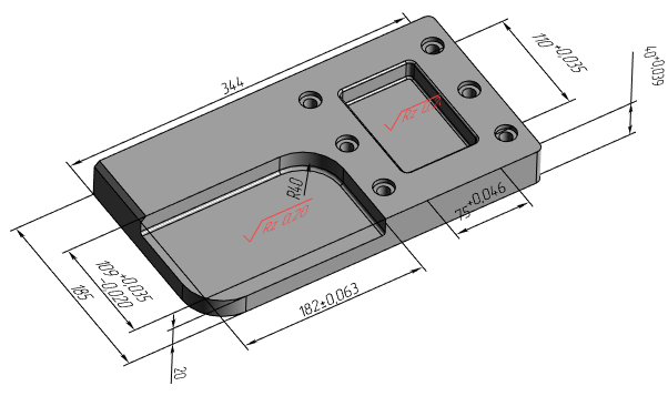
When calling the command, the system defines, which of the existing 3D dimensions in the model can be transferred to the selected view (projection). The dimensions selected by the system are drawn on the projection in red. The user needs to indicate which of the dimensions suggested by the system he would like to put on the given 2D projection.
The choice of dimensions is carried out using the options of the command automenu:
|
<M> |
Select 3D Annotation |
|
<M> |
Deselect 3D Annotation |
|
<*> |
Select all elements |
|
<End> |
Finish input |
When this option ![]() is active, the selection of dimensions that should be created on this projection is performed. It is enough to point with the cursor to the required size in the 2D window and click
is active, the selection of dimensions that should be created on this projection is performed. It is enough to point with the cursor to the required size in the 2D window and click ![]() to select a dimension. The selected size will turn blue. Thus, any number of sizes can be selected sequentially.
to select a dimension. The selected size will turn blue. Thus, any number of sizes can be selected sequentially.
Activation of this option ![]() turns on the mode of deselecting dimensions. In this mode, pointing to a dimension with
turns on the mode of deselecting dimensions. In this mode, pointing to a dimension with ![]() deselects it. As a result, the size changes its color to red again.
deselects it. As a result, the size changes its color to red again.
The effect of the option ![]() depends on which of the above options is active. When the option
depends on which of the above options is active. When the option ![]() is active, the choice of this option leads to the selection of all the dimensions proposed by the system, with the active option
is active, the choice of this option leads to the selection of all the dimensions proposed by the system, with the active option ![]() , on the contrary, to the deselection of all dimensions.
, on the contrary, to the deselection of all dimensions.
You can confirm the creation of the selected dimensions on the projection using the option ![]() .
.
Modes of displaying dimensions in 2D projections
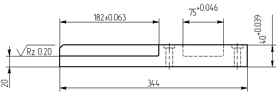
Dimensions in 2D projection lines can be displayed in two ways. The first method is the standard display of dimensions (in a plane perpendicular to the direction of view). The second way is a spatial representation of design elements. It is usually used for non-standard and volumetric views (for example, isometric). In this mode, the dimensions created from the projection lines will be drawn located in the plane of the selected elements. For example, if you are dimensioning an ellipse that corresponds to a circular edge, the dimension will be in the plane of the edge's circumference. This feature allows you to affix dimensions to isometric projections with real values.
This feature is activated by the Save Information for 3D Dimensions option on the Options tab in the 2D projection parameters. After enabling this parameter, the projection must be updated.
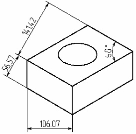
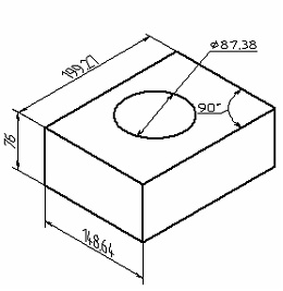
Dimensions in 2D projection in normal mode Dimensions in 2D projection in 3D mode
The spatial way of displaying dimensions in a drawing is applicable to all types of dimensions, except for level markers.
Using Projected Dimensions for Managing 3D Model
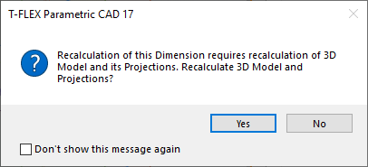
2D dimensions set on the projection, in some cases, can be used to change the 3D model. This is possible if the system was able to find a correspondence between the projection elements on which the dimension was created and the controls of the 3D model. These elements include the faces of the 3D model, which depend on the geometric parameters of the operations, or on the 2D constructions that underlie the operations of the 3D model. The system searches for such correspondence automatically when constructing dimensions on a 2D projection. If the system manages to find a correspondence, then upon changing the dimension value, the system will suggest to update 3D model and its projections in accordance with the new value. If a correspondence was not detected, then the dimension value won't be changed. Changing the dimension value is carried out using the ![]() Set value command.
Set value command.
