3D Annotations |
  
|
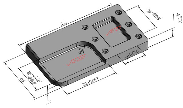
T-FLEX CAD allows creating drawing detailing elements directly on 3D model without using active workplane. Such elements are called 3D annotations. This feature is available for following elements:
Creating detailing elements in 3D scene is similar to creating them in drawing. Specifics of particular 3D detailing elements creation are described in sections, which can be accessed via links above.
Alternatively, you can create 2D detailing elements on an active workplane and then display them in 3D scene (see below).
The ability of creating 3D annotations allows instantly introducing in the 3D model not only geometrical, but also technological and other information that can later be used when creating drawings via 2D projections, as well as in other applications, for example, in the process design modules, in creating CNC machining programs. Using 3D annotations, you can design a product without creating drawings.
Displaying in 3D Scene 2D annotations belonging to a Workplane
In order to display in 3D scene 2D annotations belonging to a workplane, you need to enable the Show 2D Annotations in 3D Window checkbox in the workplane parameters dialog.
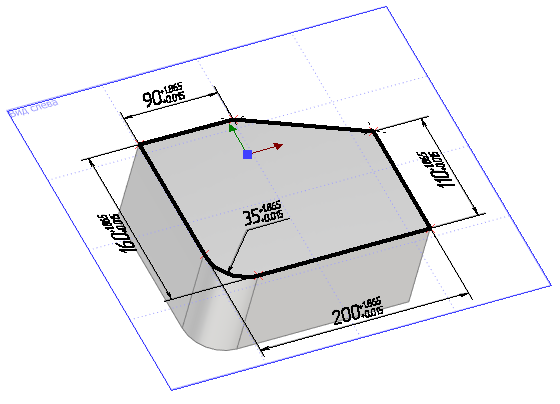
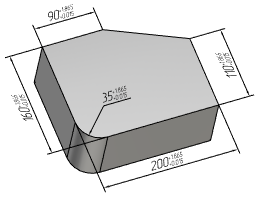
For convenience, this checkbox is also available in the contextual menu of workplane: Additional > Show 2D Annotations.
You can change values of dimensions displayed this way without activating their parent workplane. It can be used for modifying the 2D lines belonging to the workplane and, respectively, the 3D elements based on those lines (profiles, operations etc.). The system can automatically create corresponding 2D annotations on 2D projections by 2D annotations created on a workplane, if they're displayed in 3D scene and if the workplane is parallel to the 2D projection plane.
Link between 3D and 2D annotations
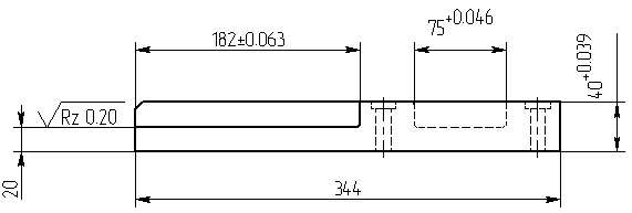
If the current 3D model has 3D dimensions or roughness symbols, then when creating 2D dimensions and roughness along the corresponding projection lines, the system can automatically find the correspondence of the created 2D element to a similar element in 3D. If such a link is found, parameters from the 3D dimension or roughness (rating, tolerance, text strings, etc.) are transferred to the 2D element being created. See more in the Link between 3D and 2D Dimensions and Link between 3D and 2D Roughness sections.
Moreover, you can automatically create 2D detailing elements corresponding to the existing 3D detailing elements. The system defines, which of the existing 3D annotations can be transferred to the selected 2D projection. Then the user selects, which elements to transfer, among the elements suggested by the system. See more in the Projecting 3D Annotations section.
Driving 3D Dimensions
3D dimensions may be used for managing geometry of 3D model. See more in the Driving 3D Dimensions section.
3D Annotations Display Options
By default, parts of 3D Annotations hidden behind non-transparent elements of a 3D model are not displayed. If necessary, you can enable the Display annotations over 3D model option (Options > 3D > 3D).
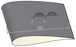
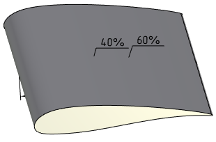
3D annotations can be hidden or displayed in a particular 3D window using the ![]() Hide/Show 3D Annotations command available in the View toolbar.
Hide/Show 3D Annotations command available in the View toolbar.
See Also: