Dimension in 3D Scene |
  
|
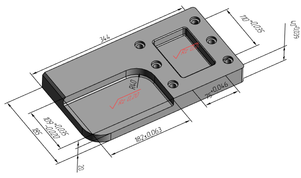
Dimensions may be created not only in a drawing and on an active workplane, but also directly in 3D space of 3D scene. 3D dimensions may be used for creating corresponding 2D dimensions, for managing 3D model geometry, or as a source of information, when designing products without creating drawings.
3D dimensions created in a part document may be individually displayed in assemblies the part is inserted to.
Creating a dimension in 3D scene

Upon calling the ![]() Dimension command, select source objects. 3D dimensions may be based on source objects of following types:
Dimension command, select source objects. 3D dimensions may be based on source objects of following types:
•faces, edges, vertices;
•axes of cylindrical faces;
•3D paths;
•3D nodes.
Objects are selected by clicking them with ![]() . Additionally you can use following automenu options for selecting source objects:
. Additionally you can use following automenu options for selecting source objects:
|
<L> |
Select Flat Face or Flat Edge |
|
<A> |
Select Axis |
|
<N> |
Select Vertex |
|
<C> |
Select Cylinder, sphere or torus |
These options activate filters for selecting elements of corresponding types.
Automenu options for selecting methods of dimension creation are not available in 3D windows. The dimension category (linear, angular, radial) is defined automatically depending on type of selected objects:
•Selecting two planes results in creating a linear dimension, if planes are parallel to each other, or an angular dimension otherwise;
•Selecting a plane and a straight line results in creating a linear dimension, if the line is parallel to the plane, or an angular dimension otherwise;
•Selecting a plane and a point results in creating a linear dimension;
•Selecting two straight lines result in creating a linear dimension, if lines are parallel to each other, or an angular dimension otherwise;
•Selecting a line and a point result in creating a linear dimension;
•Selecting two points result in creating a linear dimension;
•Selecting a single rotation surface result in creating a radial dimension.
The planes are specified by selecting a planar face or a planar curvilinear edge, the rotation surfaces – by selecting a face of revolution lying on the given surface. The straight lines are specified by selecting straight edges or the axes of the rotation surfaces. The points are specified by selecting vertices of the 3D model bodies and 3D nodes.
If user selects first a circular edge, or a face of revolution (cylinder, sphere, torus) during creating a 3D dimension, then the system will automatically start creating a radial dimension. In other cases, the system will wait for selection of the second object (point, straight line, plane, axis) for creating a linear or angular dimension. If you need to create a linear or an angular dimension between an axis of a rotation surface or a circular edge and another object, then you should either select rotation surface/circular edge as the second source object, or use the axis selection option ![]() for selecting them.
for selecting them.
Upon selecting all required objects, the preview of the dimension appears and the dimension line and value start following the cursor within degrees of freedom defined by selected object. At this stage, the dimension line and value positioning, dimension symbol and dimension linking options appear in the automenu. The selected style prescribes the number of arbitrary points defining positions of dimension line, witness lines, leader line and dimension value. These points have to be specified using ![]() .
.
When creating a linear dimension, you can specify a plane, which the dimension will lay in. To do so, activate the following automenu option, and then select the desired plane by clicking it with ![]() :
:
|
<T> |
Select Plane of Orientation |
Dimension parameters can be set in the parameters window at any stage of creating the dimension. 3D dimensions have same set of parameters as 2D dimensions. Additionally, the External checkbox is available for 3D dimensions (see below).
Same as in 2D, common 2D elements creation automenu options are available in automenu for 3D dimensions. The Finish input option can only be used during editing of an existing dimension, as creation of a new dimension finishes automatically, upon specifying all necessary points.
By default, parts of 3D dimensions as well as other 3D annotation elements hidden behind non-transparent elements of a 3D model are not displayed. If necessary, you can enable the Display annotations over 3D model option (Options > 3D > 3D).
Using fragment dimensions in assemblies
![]()
3D dimensions, created inside the fragment document, can be displayed in assemblies the part is inserted to. To do this enable the External checkbox in the Common tab of dimension's parameters dialog or in the Additional Parameters tab of the Dimension command's parameters window.
Dimensions of fragments can be used in assembly for two purposes:
•As informational - they show sizes of fragment's features;
•As driving - value of external variable of the fragment may be changed by editing the dimension value. To do this, set the nominal value of the dimension to Manually and type the name of the external variable into the adjacent input box in dimension's parameters. Editing the value of such dimension in assembly should be performed using the ![]() Set value command. Changing dimension value in dimension's parameters within assembly without calling the aforementioned command won't change the value of the variable.
Set value command. Changing dimension value in dimension's parameters within assembly without calling the aforementioned command won't change the value of the variable.
Topics in this section:
•Link between 2D and 3D Dimensions
See Also: