Collaborative Product Development in T-FLEX DOCs |
  
|
Collaborative Product Development in T-FLEX DOCs |
|
T‑FLEX DOCs provides convenient tools for collaborative product development. Multiple users can simultaneously design one assembly unit. Each of them designs his own fragment using necessary data from fragments of other users.
The design process is set up in accordance with the following workflow:
1.Chief design engineer responsible for the product creates a file of main assembly and saves it DOCs. This file will have a read-only access for other design engineers.

2.Then chief design engineer creates fragment files for other engineers within context of main assembly file, using the ![]() Create 3D Fragment command. First, a local folder, where the fragment file will be placed on the current computer, should be specified, using the
Create 3D Fragment command. First, a local folder, where the fragment file will be placed on the current computer, should be specified, using the ![]() Create 3D Fragment command's dialog.
Create 3D Fragment command's dialog.
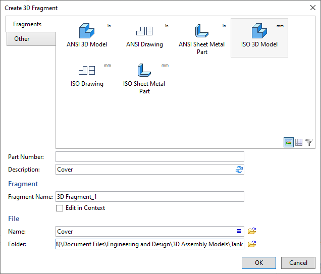
Then, upon pressing OK, the Document Saving dialog of T-FLEX DOCs appears, where the folder of the ![]() Files dataset, where the fragment file will be stored on DOCs server, should be specified.
Files dataset, where the fragment file will be stored on DOCs server, should be specified.

In order to create reference elements representing the necessary elements of main assembly within fragment files, open the created fragment file within the context of the assembly. To do this, select the fragment in the ![]() Assembly Structure tool window, then call the
Assembly Structure tool window, then call the ![]() Open in Context command from fragment's contextual menu. When working with the fragment within context of assembly, the assembly geometry is displayed in a semi-transparent mode.
Open in Context command from fragment's contextual menu. When working with the fragment within context of assembly, the assembly geometry is displayed in a semi-transparent mode.

If the Open in Context checkbox is enabled in the ![]() Create 3D Fragment command's dialog, resulting fragment file will be automatically opened within context of the assembly right after creation.
Create 3D Fragment command's dialog, resulting fragment file will be automatically opened within context of the assembly right after creation.
3.For the fragment file it is necessary to enable the ![]() Select Assembly Elements mode.
Select Assembly Elements mode.
4.Then reference elements representing the necessary elements of main assembly within fragment files should be created using the ![]() Reference Element command.
Reference Element command.
In the ![]() Parameters tool window set all parameters of reference element. If the Create geometric adaptive parameters checkbox is enabled, the created reference element is added to the geometric parameters of the fragment and the fragment becomes adaptive. In this case, when main assembly initial geometry changes, the geometry of the linked fragment changes too.
Parameters tool window set all parameters of reference element. If the Create geometric adaptive parameters checkbox is enabled, the created reference element is added to the geometric parameters of the fragment and the fragment becomes adaptive. In this case, when main assembly initial geometry changes, the geometry of the linked fragment changes too.

5.When fragment file is ready, chief design engineer calls the ![]() Save Fragment command. File will be saved to the
Save Fragment command. File will be saved to the ![]() Files dataset.
Files dataset.
6.Fragment file for another design engineer is created in the similar way.

Corresponding reference element is created in the fragment file.

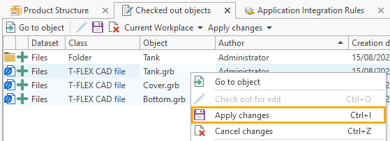
7.To make fragment files available to other engineers, chief design engineer must apply the changes to these files.
8.Chief design engineer attaches created files to tasks and sends them to other engineers. It can be done, suing the Communications > ![]() New task command available in the contextual menu of the fragment file.
New task command available in the contextual menu of the fragment file.

9.Then first and second design engineers continue with simultaneous development in the assigned files.

10.Changes in fragment files are displayed in the main assembly.
11.Product compositions of fragments are created in their files.
12.Fragment's product compositions are added to the top-level assembly's product composition using the ![]() Included Fragments command.
Included Fragments command.

13.After development works are done, changes must be applied to all objects.