Extend by Law |
  
|
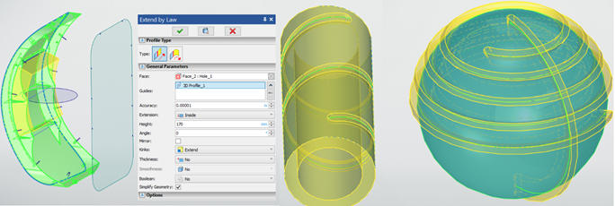
The command is designed primarily for surface modeling, but it also enables you to work with solid geometry. This command enables you to build a surface with one edge defined by a guide curve (of any complexity) that lies on a face.
This is useful when adding stiffeners to body parts that have complex spatial geometry. You do not need to perform a complex sequence of operations. It is only required to project the desired contour on the face or create a guide curve using the wire geometry commands and create the surface in one operation.
In solid modeling, the command is useful for creating grooves obtained by milling. The shape of the groove is set by the guide curve, and the width is set by the thickness parameter. If you specify the Thickness parameter, a solid body will be created instead of a surface. To create a cavity, specify a Boolean subtraction command in the command parameters. You can also round the edges of the groove to simulate the marking left by the milling cutter.
Two types of profile are available in the command: Line and Circle Arc. Two types of creating an operation are shown below: when the surface is extended by a line and an arc of a circle.
As a result, a surface is formed with optional possibility to change the angle of inclination to the surface normal. Also it is possible to add thickness and obtain a solid body with the options for rounding the edges, thereby reducing the number of clicks in some work scenarios and increasing the usability.

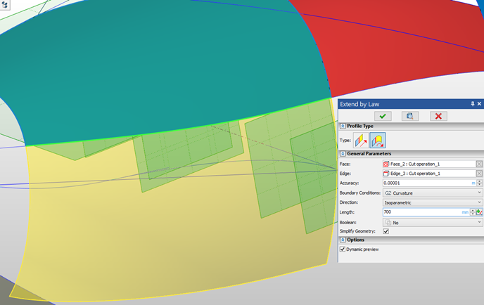
The second mode in addition includes several options. One of them creates the surface, inheriting the radius of curvature at each point of the specified edge of the face to which the continuation is created. Another one creates the surface tangent to the selected face, and user can manually specify the radius of created surface.

It is possible to define Height and Angle via a graph depending on a guide length.
Clicking the ![]() button invokes a graph type selection dialog. Then the graph can be edited using the T-FLEX CAD Graph editor.
button invokes a graph type selection dialog. Then the graph can be edited using the T-FLEX CAD Graph editor.
|
Constant height and angle |
|
Height defined via graph |
|
Angle defined via graph |