Dimension Chain |
  
|
T-FLEX CAD provides tools for creating chains of linear and angular dimensions.
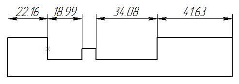
A chain of linear dimensions always starts with a straight line. First dimension represents a distance from the starting line to an another straight line parallel to the starting one. Then, each subsequent dimension in the chain represents distance between an ending object of a previous dimension and another point or line parallel to the starting line of the chain. For all dimensions in the chain, direction of measurement is normal to the starting line of the chain, and dimension lines always lay on same straight line. Moving a dimension line of a one dimension, results in moving all other dimensions belonging to the same chain, so that they stay on the same line.
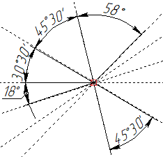
A chain of angular dimensions also always starts with a straight line. First dimension represents an angle between the starting line and another line intersecting with the starting one. Then, each subsequent dimension in the chain represents an angle between the ending line of the previous dimension and another line intersecting with the starting line of the chain in the same point, as the ending line of the first dimension. For all dimensions in the chain, dimension lines lay on the same circle centered in point of basic lines intersection. Moving a dimension line of a one dimension, results in moving all other dimensions belonging to the same chain, so that they stay on the same circle.
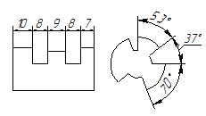
Creating new dimension chain
In order to create a dimension chain, upon calling the ![]() Dimension command, activate the following automenu option:
Dimension command, activate the following automenu option:
|
<Ctrl>+<B> |
Create Dimension Chain |
Then, you should sequentially select two straight lines, as source objects of the first dimension, by clicking them with ![]() . In result, preview of the first dimension appears. The order of objects selection defines direction of the chain. Straight line might be defined by selecting either a construction line, or a graphic line segment. A construction line may only be selected, if there is at least one 2D node on it. Upon selecting a construction line, the witness line of the resulting dimension gets snapped to the nearest 2D node laying on such such construction line; upon selecting a graphic line segment, the witness line gets snapped to the nearest endpoint of such segment.
. In result, preview of the first dimension appears. The order of objects selection defines direction of the chain. Straight line might be defined by selecting either a construction line, or a graphic line segment. A construction line may only be selected, if there is at least one 2D node on it. Upon selecting a construction line, the witness line of the resulting dimension gets snapped to the nearest 2D node laying on such such construction line; upon selecting a graphic line segment, the witness line gets snapped to the nearest endpoint of such segment.
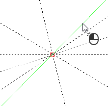
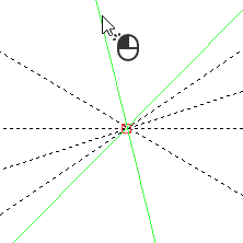
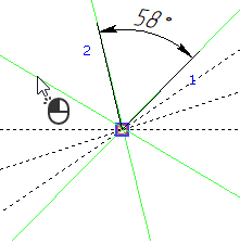


Then, you can only select those objects, which can be used for creating dimensions chained with the first dimension. For linear dimensions it is points and straight lines/segments parallel to the starting line of the chain. For angular dimensions it is straight lines and segments laying on straight lines, that intersect the starting line of the chain at the same point, as the starting line intersects with the ending line of the first dimension. A point might be defined be selecting a 2D node, characteristic point of a graphic line or intersection of construction lines. Upon selecting an intersection of construction lines or a characteristic point of a graphic line, a connected 2D node is automatically created there.
Continue selecting objects by clicking them with ![]() .
.
Straight construction lines and 2D nodes may also be selected using the following automenu options:
|
<L> |
Select Line |
|
<N> |
Select Node |
Upon activating any of these options, clicking ![]() anywhere in drawing select a nearest object of the corresponding type.
anywhere in drawing select a nearest object of the corresponding type.
Upon selecting each subsequent object, a new dimension between the selected object and the nearest object of the chain is added to the preview.
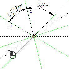
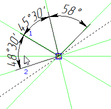


Linear dimensions might be added to the chain by both sides from the first dimension. Angular dimensions are added by one side of the starting dimension, where the side is defined by the direction of the chain.

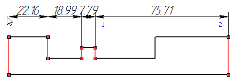
Upon selecting an object located "inside" one of the previewed dimensions, such dimension is split into two.
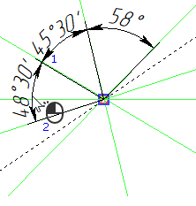
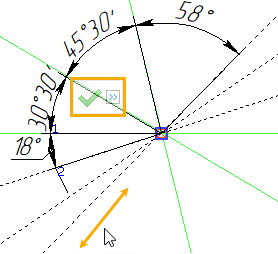

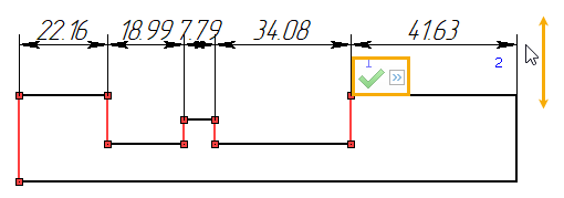
Last selection can be canceled using the following automenu option, or using the menu invoked by ![]() :
:
|
<Backspace> |
Cancel last element selection |
If you need to cancel selection of all elements and return to the initial state of the ![]() Dimension command, use the following automenu option:
Dimension command, use the following automenu option:
|
<Esc> |
Cancel selection |
As all desired dimensions are added to the preview, finish the source objects selection using the following automenu option:
|
<Ctrl>+<Enter> |
End Dimension Chain input |
Upon finishing the source objects selection, the preview of the dimension chain continues following the cursor normally to the direction of measurement.
Set the desired positions of dimension lines by moving the cursor and confirm the input by pressing ![]() or <Enter>. The dimension chain will be created. Upon creating a dimension chain, the command returns to the initial state.
or <Enter>. The dimension chain will be created. Upon creating a dimension chain, the command returns to the initial state.
During source object selection and defining position of dimension lines, the following option is available in the automenu
|
<J> |
Center Dimension Text |
For dimension chain this option works differently, compared to individual dimensions creation.
For linear dimensions, if the option is enabled, then the value of each dimension is located above the center of its dimension line, regardless of the length of such line. If the option is disabled and a length of a dimension line doesn't fit a dimension value, then a leader line of the required length is added as continuation of the dimension line, and the dimension value is placed above such leader line. The leader line is added at the "outer" side of the chain (in relation to the direction of the chain). If the current dimension is followed by another dimension, then the leader line of the current dimension overlaps the dimension line of the following dimension.
For angular dimensions, on contrary, continuations of dimension lines are added, if the option is enabled. However, regardless of the state of the option, if a value doesn't fit a dimension line, then a leader line with shoulder is automatically added to the center of the dimension line and the value is placed above such shoulder.
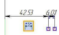
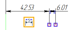
Upon finishing source objects selection, common options of 2D elements creation commands also appear in the automenu.
Adding dimensions to an existing chain
The following automenu option is available upon entering the dimension chain creation mode:
|
<D> |
Select dimension in chain |
Activate it, and then select one of the dimensions belonging to the chain, which you want to complement, by clicking it with ![]() . Then, select two source object of the dimension, that should be added first. It is OK for the chain to have a break, if none of the selected objects are related to ends of the chain. Upon selecting source objects of the first dimension, subsequent dimensions are added by selecting a single object, same as when creating a new chain. Further actions are also similar to creation of a new chain. Upon finishing the chain supplementing, dimension lines of old dimensions in the chain are aligned with dimension lines of added dimensions.
. Then, select two source object of the dimension, that should be added first. It is OK for the chain to have a break, if none of the selected objects are related to ends of the chain. Upon selecting source objects of the first dimension, subsequent dimensions are added by selecting a single object, same as when creating a new chain. Further actions are also similar to creation of a new chain. Upon finishing the chain supplementing, dimension lines of old dimensions in the chain are aligned with dimension lines of added dimensions.
When adding dimensions to a chain, selected source objects should lay by the same side of the chain. Otherwise dimension lines of new dimensions will overlap old dimension lines.
Parameters and editing of dimensions belonging to a chain
During chain creation, the content of the parameters window and parameters dialog is related to all dimensions of the current chain. After chain creation, each dimension is a separate element, so its parameters can be edited separately from parameters of other dimensions.
Alignment of dimension lines in a chain is kept during dimensions' editing. I.e., if you move dimension line of a one dimension, dimension lines of the whole chain will move accordingly.
Only the first dimension of the chain has two witness lines. Subsequent dimensions do not have witness lines near the previous dimension.
There is an associative link between dimensions in the chain: each subsequent dimension is a child of the previous one. Therefore, you can delete the whole chain by deleting its first dimension.