Unfolded View (Flat Pattern Projection) |
  
|
The command can be called in one the following ways:
Icon |
Ribbon |
|---|---|
|
Draw > 2D Projection > Flat Pattern Projection Sheet Metal (2D) > Draw > Flat Pattern Projection Sheet Metal (3D) > Additional > Flat Pattern Projection |
Keyboard |
Textual Menu |
<3PF> |
Operation > Sheet Metal > Flat Pattern Projection Draw > 2D Projection > Flat Pattern Projection |
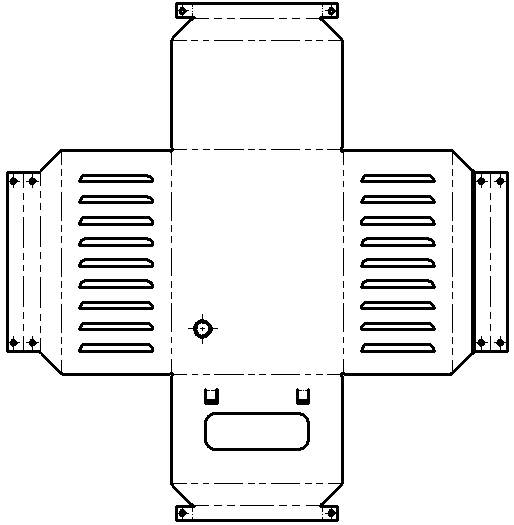
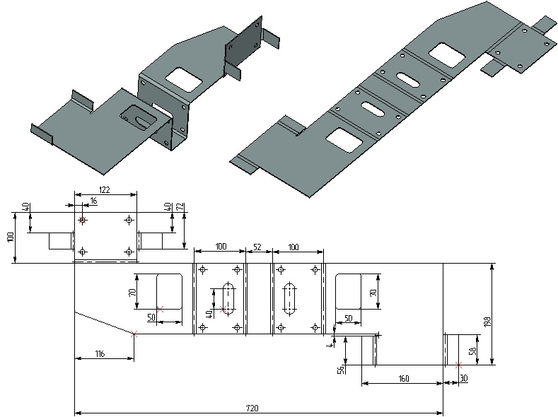
The command creates an unfolded drawing view of a sheet metal part. The command is available in the ribbon, when a 2D view window is active and when drawing on an active workplane.
If necessary, folded and unfolded views of the sheet part can be placed at the same drawing page.

The interface of the Flat Pattern Projection command is similar to the interface of the Arbitrary View command. However, unlike the latter, the flat pattern projection's view direction is defined automatically in such way, so it is normal to the unfolding. A view label containing the symbol of unfolding ![]() is created automatically for flat pattern projection. You can edit or delete the label, if necessary.
is created automatically for flat pattern projection. You can edit or delete the label, if necessary.

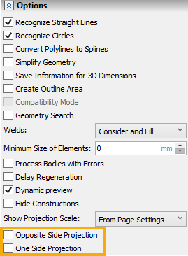
In addition to common projection controls, there are following checkboxes available in the Options tab of the command's parameters window:
•Opposite Side Projection
Switches view direction to an opposite one.
•One Side Projection
Projects only the set of faces (surfaces) visible from the view direction instead of the whole solid body. It helps to avoid the occurrence of breaks and extra lines in some complex cases, and speeds up the recalculation of the projection.
To display bending zones on the projection, it is necessary to disable the Simplify Geometry flag on the Additional tab in the projection parameters and enable the Smooth edges flag on the Lines tab. To display the bending centerlines, enable the Axial lines flag on the Lines tab.
