Conventions Adopted in the T-FLEX CAD Help |
  
|
The following standard conventions are adopted in this document:
Keys on the keyboard are highlighted in semi-bold font and angle brackets:
<Enter>, <Esc>
Keyboard shortcuts, which require to press buttons sequentially one by one, (hotkey sequences) are shown in common angle brackets without any spacing between separate keys:
<3G>, <3RG>
Keyboard shortcuts, which require to press buttons simultaneously, (hotkey combinations) are shown by addition of separate key designations:
<Alt>+<F4>, <Ctrl>+<Z>
|
Left mouse button click. |
|
Right mouse button click. |
|
Left mouse button double-click. |
|
Mouse wheel scrolling |
|
Mouse wheel click (middle mouse button) |
|
Command icon |
|
Other icons (automenu options, command parameters etc.) |
Names displayed in the T-FLEX CAD interface are highlighted in semi-bold font. It might be names of commands (Extrusion, Line), dialog box buttons (OK, Cancel), various options (Select Faces, Object Snap), input boxes (Length:, Angle:) etc.
File > Open… etc. – selection of a textual menu bar item File, followed by a pull-down menu item Open….

A command can be invoked in T-FLEX CAD in several ways. There are three main ways:
•typing hotkeys from the keyboard,
•clicking the command's icon in the ribbon or in a toolbar of textual interface,
•using the textual menu.
Main ways of invoking the command are shown in a table view in the beginning of a command's description. For instance, the Layers command's description begins with the following table:
Icon |
Ribbon |
|---|---|
|
Get Started > Options > Tool Windows > Layers 3D Model > Style > Layers Draw > Style > Layers Assembly > Style > Layers Sheet Metal > Style > Layers Surfaces > Style > Layers Weld > Style > Layers Routing > Style > Layers Primitives > Style > Layers Support Geometry > Style > Layers Edit > Document > Layers View > Window > Tool Windows > Layers Remarks > Style > Layers Workplane > Style > Layers
|
Keyboard |
Textual Menu |
<QL>, <Shift>+<F5> |
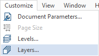
Customize > Layers |
This means, the command can be invoked in the following ways:
•Press sequentially <Q> then <L> keys on the keyboard;
•Press simultaneously <Shift> and <F5> keys on the keyboard;
•Select the Customize item in the textual menu and then select the Layers… command from the drop-down list.

•Select the icon ![]() in the corresponding toolbar.
in the corresponding toolbar.

•Select the Layers command in the Document group in the Edit tab of the ribbon.

•Select the Layers command in the Style group in one of the following tabs of the ribbon: 3D Model, Draw, Assembly, Sheet Metal, Surfaces, Weld, Routing, Primitives, Support Geometry, Remarks, Workplane. The Assembly and the Sheet Metal tabs may have different content, depending on the active view window. If a command is accessible in a tab only for 2D or only for 3D view, then (2D) or (3D) respectively is added to the name of the tab in the command call table.

•Select the Layers command in the drop-down menu, which appears upon selecting the Tool Windows command in the Window group in the View tab of the ribbon or in the Options group in the Get Started tab of the ribbon.
•Click the ![]() button of the system customization menu located in the upper right corner of the window in ribbon interface, then move the cursor over the Tool Windows menu item and select the Layers command in the appeared drop-down menu.
button of the system customization menu located in the upper right corner of the window in ribbon interface, then move the cursor over the Tool Windows menu item and select the Layers command in the appeared drop-down menu.
Commands may also be called from contextual menus or from the Dynamic Toolbar.
Select an element instruction in the manuals means placing the cursor over the element and pressing left mouse button ![]() .
.
Select an icon, press an icon, select an input box, press a button instruction means placing the cursor over the item (icon, input box, dialog box button) and pressing left mouse button ![]() .
.
Point at an element, point at an icon, point at a button means just placing the cursor over the item.
Each command usually brings a list of options available under this command. An option is one specific action performed within the command, as delete an element, select an element of a particular type, switch to another mode, etc.
Each option has a hotkey and an icon in the automenu.
Invoking an option using a hotkey might be different from using an automenu icon. Using a hotkey instantly invokes the action, while selecting an icon may work in two ways.
First possibility – an instant action occurs, as, for instance, when specifying parameters of an element - ![]() .
.
Second possibility – after selecting the icon, the system waits for a specific user action, and a symbol representing the required action appears near the cursor. The action completes when the cursor is pointed at an appropriate element and left mouse button ![]() pressed. For instance, this can be a selection of a construction line –
pressed. For instance, this can be a selection of a construction line – ![]() .
.

In 2D drawing commands "press ![]() " usually means that you can press either left mouse button
" usually means that you can press either left mouse button ![]() or the <Enter> key.
or the <Enter> key.
In 3D modeling commands it works in a similar way upon selecting a geometry, which is mandatory for creating an operation, but it doesn't work upon selecting an optional geometry (pressing <Enter> after selecting a mandatory geometry leads to completing a creation of an operation).