Work with 3D Fragment |
  
|
In the course of working with an assembly, you may need to access auxiliary information about the state of 3D fragments. This can be querying their position in the assembly tree, reviewing existing errors, etc. Various tools are provided for this purpose. We will review those tools within the current topic.
3D fragments and Parts are displayed in the 3D Model window. This window shows the complete hierarchy of the assembly model. It allows finding the place of each 3D fragment in the model structure among other 3D operations and construction elements. 3D fragments can be displayed at the root of the model structure, along with Bodies and Arrays.
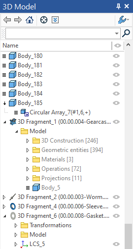
If a 3D fragment is an assembly itself, containing embedded 3D fragments, the structure of all its embedded elements is reflected in the general 3D model tree as well. For embedded fragments of any level the commands of editing external variables and creation of detail drawing are available in the context menu.
To ensure the full support of handling the embedded 3D fragments, you need to bring into the editing environment the subassembly that hosts the fragment of interest.
Embedded fragments can also be selected directly in the 3D scene. The special ![]() Select embedded subassemblies by bodies mode of selection allows to select separate bodies of sublassemblies' fragments. You can open fragment's document, start detailing or editing variables of a selected fragment.
Select embedded subassemblies by bodies mode of selection allows to select separate bodies of sublassemblies' fragments. You can open fragment's document, start detailing or editing variables of a selected fragment.
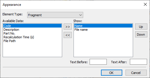
In the 3D Model window for 3D fragments, besides the name of the file and the operation, various additional information can be shown, if needed, – file path, identifier, memory size allocated for mesh, memory usage for geometry, recalculation time, the name and notation for specification. The amount of displayed information can be set in the dialog box of the Appearance command. This command can be called from the context menu by pressing ![]() in the 3D Model window.
in the 3D Model window.
If errors are detected in the model, the affected elements are marked in the model tree with the special symbols:
1.If an error was detected within a 3D fragment model or its coordinate systems, a mark is displayed.
2.The 3D fragments, whose files were not found by the specified reference, are marked by a red cross.
![]()
3.The suppressed 3D fragments are marked by a blue cross.
![]()
When suppressing fragments or an array/copies/symmetries of fragments in the 3D model tree, suppression immediately extends to all reference elements, raised objects and created fragments.

Detailed information about all errors is displayed in the Diagnostics window. Right clicking ![]() over a message brings up the context menu. If the message refers to a 3D fragment of the first level, then you have access to all commands for handling that 3D fragment. If the message reports an error within embedded fragments, then the only command for handling the fragment is Show Fragment Structure.
over a message brings up the context menu. If the message refers to a 3D fragment of the first level, then you have access to all commands for handling that 3D fragment. If the message reports an error within embedded fragments, then the only command for handling the fragment is Show Fragment Structure.
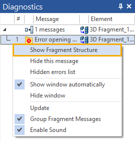
The fragment, within which the error was identified, is automatically highlighted, showing the branch of the assembly tree that includes the failing fragment.
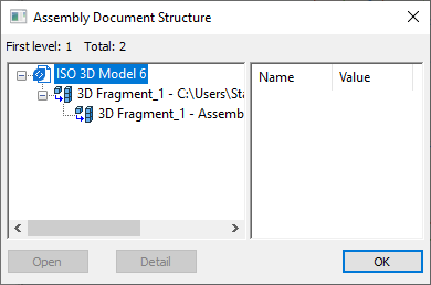
The right pane of the window displays the information about variables used in the fragment: their names, values and comments. To fix the error in the fragment file, you can open the file by pressing the Open button. For example, the error in the fragment model can be caused by an invalid variable value. To open the fragment with the current variable values use the Detail button.
Normally, the assembly tree displays only its contributing 3D fragments. To view the full assembly structure, use the Assembly Structure window.
Reference update
Let us explain the use of the option Update fragment data.
When inserting a 3D fragment, the system internally creates a copy of the fragment three-dimensional model in the assembly drawing. Upon a new regeneration of the assembly, the system no longer loads the 3D fragment geometry data; rather, it uses the saved data. To maintain the assembly up to date, the system constantly tracks the file. The latter changes if the fragment file was edited and saved. If files changed, the system instantly offers updating the references to the documents, that is, loading new geometry data of the modified 3D fragments.
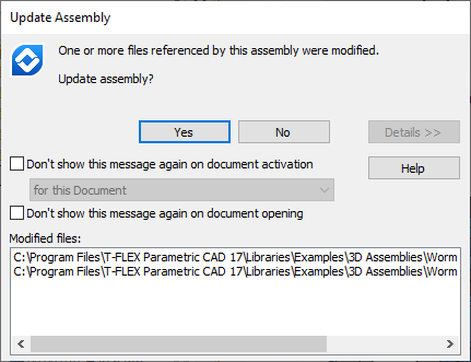
Pressing the Yes button refreshes the data of all modified fragments. If the assembly contains a significant number of fragments, the updating procedure may take significant time, even though only one fragment actually required update. Therefore, you can press the No button instead, and then select a specific fragment and refresh only its respective data.
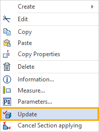
Local update of a selected 3D fragment is possible with the Update command of the context menu coming up upon right clicking ![]() over the 3D fragment operation.
over the 3D fragment operation.
Updating of all modified fragments can be forced by the Move Assembly > Update Links command in the Assembly ribbon tab, Component Links group.
However, if some of the 3D fragment files were not modified, then the 3D fragments are regenerated neither upon the full regeneration nor upon refreshing the 3D fragment references. To guarantee the regeneration of the full assembly with all its member 3D fragments, use the file converter with the parameter set, Don't Check Documents Versions (Resave All).