Semi-Connected 2D Node |
  
|
A position of ![]() a semi-connected node is defined by offsets in relation to construction lines or to other nodes.
a semi-connected node is defined by offsets in relation to construction lines or to other nodes.
Following methods of creating ![]() semi-connected 2D nodes are available in the Node command:
semi-connected 2D nodes are available in the Node command:
•Node by dX and dY offsets from another node
•Node by offset along a construction line from another node
•Node splitting a construction curve in a specified ratio
•Node splitting a distance between two other nodes in a specified ratio
•Node splitting a distance between two other nodes on a curve in a specified ratio
Creation of semi-connected nodes (except the node splitting a construction curve in a specified ratio) works equally well in the ![]() connected and
connected and ![]() free modes regardless of the object snappings status.
free modes regardless of the object snappings status.
Node by dX and dY offsets from another node
Select an existing 2D node either by moving the cursor over it and pressing ![]() or <Enter>, or using the following automenu option:
or <Enter>, or using the following automenu option:
|
<N> |
Select Node for relative Node creation |
Upon selecting an existing node, the preview of the new node starts following the cursor. Link between the new and the existing nodes is indicated by the blue line.

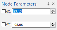
The parameters window contains input boxes of dX and dY offset of the new node in relation to the selected one.

Specify the position of the new node either by placing the cursor over the desired position in the drawing window and pressing ![]() or <Enter>, or by typing offset values into the parameters window.
or <Enter>, or by typing offset values into the parameters window.
Typing in an offset value enables a checkbox located near the offset's input box. Enabling the checkbox fixates the offset value, so it no longer depends on the cursor position. In result, the preview of the new node can only be moved along a horizontal or vertical line corresponding to the specified offset value. Such line is displayed in blue dashes. Fixating values of both offset prevents further node's preview movement, so it stays at the intersection of corresponding dashed blue lines. Then you should press <Enter> or click ![]() anywhere within the drawing window, in order to create a node.
anywhere within the drawing window, in order to create a node.
Node by offset along a construction line from another node
Select an existing 2D node, which lays on a construction line, either by moving the cursor over it and pressing ![]() or <Enter>, or using the following automenu option:
or <Enter>, or using the following automenu option:
|
<N> |
Select Node for relative Node creation |
Next, select the construction line, which the node lays on, either by moving the cursor over it and pressing ![]() or <Enter>, or using one of the following automenu options:
or <Enter>, or using one of the following automenu options:
|
<L> |
Select Line to Create Node |
|
<C> |
Select Circle to Create Node |
|
<E> |
Select Ellipse to Create Node |
|
<S> |
Select Spline to Create Node |
The preview of the new node will start following the cursor along the selected line.

The parameters window will contain the input box of the Distance (in absolute units) between the selected node and the new one.

Specify the position of the new node either by placing the cursor over the desired position in the drawing window and pressing ![]() or <Enter>, or by typing a distance value into the parameters window.
or <Enter>, or by typing a distance value into the parameters window.
Typing in a distance value enables the checkbox located near the distance input box. Enabling the checkbox fixates the position of the new node, so it no longer depends on the cursor position. Then you should press <Enter> or click ![]() anywhere within the drawing window, in order to create a node.
anywhere within the drawing window, in order to create a node.
Node splitting a construction curve in a specified ratio
For circles and ellipses this method of creating semi-connected nodes is only possible in the ![]() free mode. Same actions in the connected node would result in creation of a connected node at the center. For other types of lines this method works equally well in both modes.
free mode. Same actions in the connected node would result in creation of a connected node at the center. For other types of lines this method works equally well in both modes.
Select the construction line, which the node lays on, either by moving the cursor over it and pressing ![]() or <Enter>, or using one of the following automenu options:
or <Enter>, or using one of the following automenu options:
|
<L> |
Select Line to Create Node |
|
<C> |
Select Circle to Create Node |
|
<E> |
Select Ellipse to Create Node |
|
<S> |
Select Spline to Create Node |
The preview of the new node will start following the cursor along the selected line.

The parameters window will contain the input box of the Coefficient. The coefficient is the distance along the curve between the curve's start and the created node divided by the full length of the curve.

Specify the position of the new node either by placing the cursor over the desired position in the drawing window and pressing ![]() or <Enter>, or by typing a coefficient value into the parameters window.
or <Enter>, or by typing a coefficient value into the parameters window.
When pressing ![]() or <Enter>, if the cursor is near other other construction line intersecting the selected curve, then the connected node gets created at the intersection point.
or <Enter>, if the cursor is near other other construction line intersecting the selected curve, then the connected node gets created at the intersection point.
Typing in a coefficient value enables the checkbox located near the coefficient input box. Enabling the checkbox fixates the position of the new node, so it no longer depends on the cursor position. Then you should press <Enter> or click ![]() anywhere within the drawing window, in order to create a node.
anywhere within the drawing window, in order to create a node.
Node splitting a distance between two other nodes in a specified ratio
Select two existing 2D nodes one by one, either by moving the cursor over them and pressing ![]() or <Enter>, or using the following automenu option:
or <Enter>, or using the following automenu option:
|
<N> |
Select Node for relative Node creation |
The preview of the new node will start following the cursor along the straight line passing through selected nodes.

The parameters window will contain the input box of the Coefficient. The coefficient is the distance between the first selected node and the new node divided by the distance between two selected nodes. If the coefficient value is lower than zero or higher than one, the new node is created at the same side in relation to the two selected nodes.

Specify the position of the new node either by placing the cursor over the desired position in the drawing window and pressing ![]() or <Enter>, or by typing a coefficient value into the parameters window.
or <Enter>, or by typing a coefficient value into the parameters window.
Typing in a coefficient value enables the checkbox located near the coefficient input box. Enabling the checkbox fixates the position of the new node, so it no longer depends on the cursor position. Then you should press <Enter> or click ![]() anywhere within the drawing window, in order to create a node.
anywhere within the drawing window, in order to create a node.
Node splitting a distance between two other nodes on a curve in a specified ratio
Select an existing 2D node, which lays on a construction line, either by moving the cursor over it and pressing ![]() or <Enter>, or using the following automenu option:
or <Enter>, or using the following automenu option:
|
<N> |
Select Node for relative Node creation |
Next, select the construction curve (circle, ellipse, path, spline, offset curve, function spline), which the node lays on, either by moving the cursor over it and pressing ![]() or <Enter>, or using one of the following automenu options:
or <Enter>, or using one of the following automenu options:
|
<C> |
Select Circle to Create Node |
|
<E> |
Select Ellipse to Create Node |
|
<S> |
Select Spline to Create Node |
The preview of the new node will start moving between selected nodes along the selected line following the cursor. The parameters window will contain the input box of the Coefficient. The coefficient is the distance along the selected curve between the first selected node and the new node divided by the full distance along the curve between two selected nodes. For an open curve, if the coefficient value is lower than zero or higher than one, the new node is created at the same side in relation to the two selected nodes. For a closed curve, the coefficient is always fits in zero to one range, but can be applied to any of the two sections between the selected nodes depending on the cursor's position.

Specify the position of the new node either by placing the cursor over the desired position in the drawing window and pressing ![]() or <Enter>, or by typing a coefficient value into the parameters window.
or <Enter>, or by typing a coefficient value into the parameters window.
Typing in a coefficient value enables the checkbox located near the coefficient input box. Enabling the checkbox fixates the position of the new node, so it no longer depends on the cursor position. Then you should press <Enter> or click ![]() anywhere within the drawing window, in order to create a node.
anywhere within the drawing window, in order to create a node.