Connected 2D Node |
  
|
A position of a ![]() connected node is fully defined by positions of other 2D elements.
connected node is fully defined by positions of other 2D elements.
Following methods of creating ![]() connected 2D nodes are available in the Node command:
connected 2D nodes are available in the Node command:
•at the intersection of selected construction lines
•at the nearest intersection of construction lines
•at the center of a construction circle or ellipse
•at the endpoint of a construction curve
•at key point of graphic lines
•at key point of drawing detailing elements
•on a construction line linked to a graphic line
Moreover, connected nodes might be created in other commands:
•Construction elements creation and editing commands: Line, Circle, Ellipse, Path, Spline, Offset Curve, Function Spline, Edit Node, Edit 2D Constructs
Pressing <Space> automatically creates a connected node at the nearest (to the cursor) intersection of construction lines.
When snapping elements created by this commands to intersections of construction lines, centers of construction circles/ellipses, key points of graphic lines belonging to 2D fragments or 2D projections, connected nodes are created automatically at such points. Moreover, when creating a pair of perpendicular lines, a connected 2D node is created automatically at their intersection.
•Graphic Line
Pressing <Space> automatically creates a connected node at the nearest (to the cursor) intersection of construction lines.
When creating graphic lines in connected drawing mode, connected nodes are created automatically at selected intersections of construction lines, centers of construction circles/ellipses, key points of graphic lines belonging to 2D fragments or 2D projections.
•Hatch
Pressing <Space> automatically creates a connected node at the nearest (to the cursor) intersection of construction lines.
When drawing the hatch contour in the manual mode, connected nodes are created automatically at selected intersections of construction lines, centers of construction circles/ellipses, key points of graphic lines belonging to 2D fragments or 2D projections.
•Sketch
When snapping created elements to intersections of construction lines or centers of construction circles/ellipses, connected nodes are created automatically at such points.
Node at the intersection of selected construction lines
With object snappings disabled
This method of nodes creation works equally well in the ![]() connected and
connected and ![]() free modes.
free modes.
Move the cursor over a construction line and press ![]() , <Enter> or a hot key of an automenu option corresponding to the type of the line.
, <Enter> or a hot key of an automenu option corresponding to the type of the line.
Following automenu options can be used for selecting lines:
|
<L> |
Select Line to Create Node |
|
<C> |
Select Circle to Create Node |
|
<E> |
Select Ellipse to Create Node |
|
<S> |
Select Spline to Create Node |
The spline selection option may also be used for selecting a 2D path, offset curve or function spline.
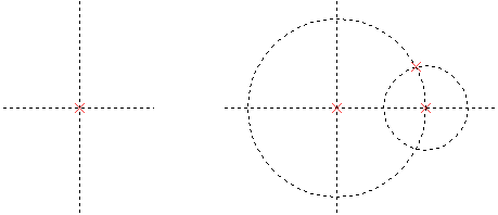
The preview of the node will start following the cursor along the selected line. Next, move the cursor over an another construction line, which intersects the previously selected line, and again press ![]() , <Enter> or a hot key of an automenu option corresponding to the type of the second line. A connected node
, <Enter> or a hot key of an automenu option corresponding to the type of the second line. A connected node ![]() will be created at the intersection of selected lines. If there are more than one intersections, the node gets created at the intersection nearest tot the cursor.
will be created at the intersection of selected lines. If there are more than one intersections, the node gets created at the intersection nearest tot the cursor.
With object snappings enabled
This method of nodes creation works equally well in the ![]() connected and
connected and ![]() free modes.
free modes.
If the object snapping is enabled, you can directly select an intersection of construction lines instead of selecting lines individually. Move the cursor over an intersection and click ![]() it to create a node there.
it to create a node there.


Node at the nearest intersection of construction lines
Using the <Space> key
Both in the ![]() connected and
connected and ![]() free modes pressing <Space> creates a
free modes pressing <Space> creates a ![]() connected node at the nearest (to the cursor) intersection of construction lines.
connected node at the nearest (to the cursor) intersection of construction lines.
Using the <Enter> key
In the ![]() connected mode pressing <Enter>, when none of the elements are selected or pre-selected, creates a
connected mode pressing <Enter>, when none of the elements are selected or pre-selected, creates a ![]() connected node at the nearest (to the cursor) intersection of construction lines.
connected node at the nearest (to the cursor) intersection of construction lines.
Node at the center of a construction circle or ellipse
With object snappings disabled
In the ![]() connected mode move the cursor over a circle or ellipse and press
connected mode move the cursor over a circle or ellipse and press ![]() , <Enter> or a hot key of an automenu option corresponding to the type of the line.
, <Enter> or a hot key of an automenu option corresponding to the type of the line.
Following automenu options can be used for selecting circles and ellipses:
|
<C> |
Select Circle to Create Node |
|
<E> |
Select Ellipse to Create Node |
The preview of the node will start following the cursor along the selected circle/ellipse. In order to finish the node creation, again press ![]() , <Enter> or a hot key of an automenu option corresponding to the type of the line.
, <Enter> or a hot key of an automenu option corresponding to the type of the line.
When using the ![]() for finishing the node creation, the result depends on the cursor position. If the cursor is far from construction lines intersecting the selected circle/ellipse, then the node gets created at the center, otherwise - at the intersection point. When using hot keys for finishing the node creation, the node gets created at the intersection point, only if the intersecting line belongs to the type corresponding to the applied automenu option.
for finishing the node creation, the result depends on the cursor position. If the cursor is far from construction lines intersecting the selected circle/ellipse, then the node gets created at the center, otherwise - at the intersection point. When using hot keys for finishing the node creation, the node gets created at the intersection point, only if the intersecting line belongs to the type corresponding to the applied automenu option.
With object snappings enabled
This method of nodes creation works equally well in the ![]() connected and
connected and ![]() free modes.
free modes.
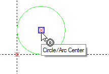
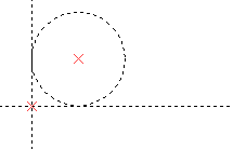
Move the cursor over a center of a circle or ellipse and click it ![]() . A connected node
. A connected node ![]() will be created at the center.
will be created at the center.
Node at the endpoint of a construction curve
This method of nodes creation works equally well in the ![]() connected and
connected and ![]() free modes regardless of object snappings status.
free modes regardless of object snappings status.
Select a spline, 2D path, offset curve or function spline using either ![]() , <Enter> or the following automenu option:
, <Enter> or the following automenu option:
|
<S> |
Select Spline to Create Node |
The preview of the node will start following the cursor along the selected curve.
Next, activate the following option:
|
<T> |
Select Curve to create end Node |
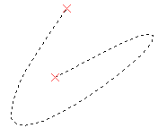
If the option is activated via keyboard, then the ![]() connected node gets created instantly at the nearest (to the cursor) endpoint of the selected curve.
connected node gets created instantly at the nearest (to the cursor) endpoint of the selected curve.
If the option is activated via mouse, then you have to click ![]() again within the drawing window. In result, the
again within the drawing window. In result, the ![]() connected node gets created at the endpoint nearest to the point of clicking.
connected node gets created at the endpoint nearest to the point of clicking.
Node at key point of graphic lines
This method of nodes creation works equally well in the ![]() connected and
connected and ![]() free modes.
free modes.
Select ![]() the desired point of graphic lines using the object snappings. The
the desired point of graphic lines using the object snappings. The ![]() connected node will be created at the selected point. If the selected point belongs to the line projected from 3D model, then the created node will keep link with the model, i.e.: upon changing the model geometry, the position of the node might change correspondingly after regenerating the projection. If the projected feature of the model gets deleted, then the 2D node gets deleted too after regenerating the projection.
connected node will be created at the selected point. If the selected point belongs to the line projected from 3D model, then the created node will keep link with the model, i.e.: upon changing the model geometry, the position of the node might change correspondingly after regenerating the projection. If the projected feature of the model gets deleted, then the 2D node gets deleted too after regenerating the projection.


Node at key point of drawing detailing elements
This method of nodes creation works equally well in the ![]() connected and
connected and ![]() free modes regardless of object snappings status.
free modes regardless of object snappings status.
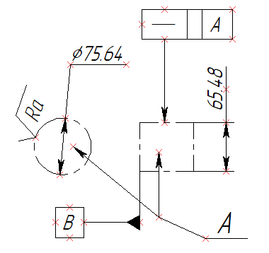
As you move the cursor over key points of dimensions, leader notes, GD&T and roughness symbols, said points are highlighted. Click a highlighted point or press <Enter> to create a ![]() connected node there. The node will keep link with the detailing element.
connected node there. The node will keep link with the detailing element.
Node on a construction line linked to a graphic line
In the ![]() connected mode select using
connected mode select using ![]() or <Enter> the desired graphic line.
or <Enter> the desired graphic line.
If you selected a straight line, then the coinciding straight construction line will be automatically created. Connected nodes ![]() will be automatically created at the endpoints of the selected line
will be automatically created at the endpoints of the selected line
If you selected a circle or a circular arc, then the coinciding construction circle will be automatically created. Click ![]() or press <Enter> again to create a
or press <Enter> again to create a ![]() connected node at the center of the circle.
connected node at the center of the circle.
During the second click, if the cursor is near a construction line intersecting the selected circle, then the ![]() node gets created at the intersection point.
node gets created at the intersection point.
If you selected an ellipse or an elliptical arc, then the coinciding construction ellipse will be automatically created. Click ![]() or press <Enter> again to create a
or press <Enter> again to create a ![]() connected node at the center of the ellipse.
connected node at the center of the ellipse.
During the second click, if the cursor is near a construction line intersecting the selected epllipse, then the ![]() node gets created at the intersection point.
node gets created at the intersection point.
If you selected a spline, then the coinciding construction spline will be automatically created. Then you can create a ![]() semi-connected node splitting the spline in the specified ratio.
semi-connected node splitting the spline in the specified ratio.
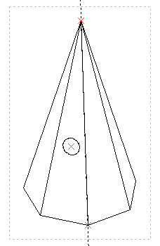
If the selected graphic line is projected from 3D model, then the created construction line and, therefore, the node will keep link with the model, i.e.: upon changing the position of the corresponding model feature, the position of the construction line and node change after regenerating the projection. If the projected feature of the model is deleted, then linked construction lines and 2D nodes get deleted too after regenerating the projection.
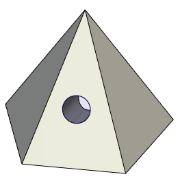
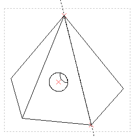
2D nodes are created at the ends of the pyramid's edge and at the center of the hole
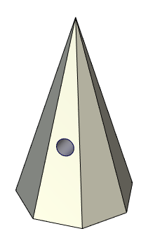
Upon changing the model geometry, positions of 2D nodes and construction lines have been updated