Offset Curve. 2D Constructs |
  
|
The command can be called in one of the following ways:
Icon |
Ribbon |
|---|---|
|
Draw > Construct > Offset Curve Workplane > Construct > Offset Curve |
Keyboard |
Textual Menu |
<TO> |
Construct > Offset Curve |
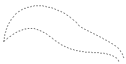
Offset curve is a curve offset from the original curve, at a distance specified by a number or function (as a graph). If the offset is set by a number, i.e. it is constant, then such an offset curve will be equidistant. The source curve can be an ellipse, spline, function, or path.
The most typical application of the offset curve is pipelines creation. It is convenient to draw only the center line, and then build equidistant lines of the contours of the pipe itself. In addition, offset curves are widely used in the development of the building and architectural drawings.
Creating Offset Curves
Upon entering the command, the following actions become available:
|
<Enter> |
Select element |
|
<P> |
Set Construction Line parameters |
|
<E> |
Select Spline |
|
<S> |
Select Ellipse |
|
<F4> |
|
|
<Esc> |
Exit command |
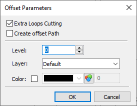
Before creating an offset curve you can call the parameters dialog via the ![]() <P> option. The dialog's layout prior to starting the construction differs from the layout of the dialog called either after selecting the base element, or for an already created curve:
<P> option. The dialog's layout prior to starting the construction differs from the layout of the dialog called either after selecting the base element, or for an already created curve:

In addition to the general system parameters (Level, Layer, Color) the dialog contains following parameters:
•Extra Loops Cutting
If the checkbox is enabled, then loops formed on the contour of the offset curve are deleted.
•Create offset Path
This option is applicable, when constructing an offset curve from a 2D path. When the checkbox is enabled, the resulting offset curve will be converted into the path. The already created offset curve cannot be converted to a path, so the checkbox should be enabled before the construction is completed.
Creation of the offset curve begins with the selection of the base element, relative to which it is necessary to construct the curve. The base element is selected using the ![]() .
.
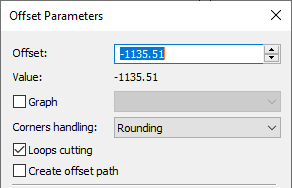
The selected element is highlighted and the dynamically moving image of the offset curve appears. The equidistant is created by default, since the offset specified by the cursor is a constant value. After that, you need to move the cursor to the necessary position and click ![]() or use the option <P>. In the latter case, the parameters dialog will appear on the screen. In addition to the parameters mentioned above, the dialog will contain following parameters:
or use the option <P>. In the latter case, the parameters dialog will appear on the screen. In addition to the parameters mentioned above, the dialog will contain following parameters:
•Offset
The distance between the created curve and the base element. The sign of the offset defines the direction. The initial value of the parameter is defined by the position of the cursor. If an offset curve is snapped to a 2D node, then the offset value becomes zero and it cannot be edited.
•Value
This field displays the numerical value of the Offset, which may be useful, when offset is defined by a variable or an expression.


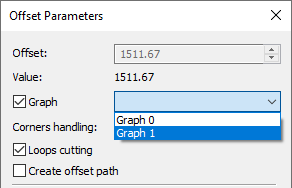
•Graph
This option is applied for creating an offset curve with a variable offset. Upon enabling the checkbox, you can select in the drop-down list any of the graphs available in the current document. The graph should be created in advance. The graph argument will specify the position of the point along the length of the base curve, the graph function will set the offset for this point. The first value of the argument will correspond to the first point of the base curve, the last value will correspond to the last point. Intermediate values of the argument will be distributed along the length of the base curve according to their relative value to the first and last value of the argument. The offset along the length of the original curve in the areas between the points specified by the graph will be calculated according to the type of the graph: polyline, smooth curve or function. Detailed information on creating graphs may be found in the Graphs section. Upon enabling the Graph checkbox, the Offset input box becomes inactive.


•Corners handling
One of the following options can be selected in the drop-down list:
|
|
|
Rounding |
By tangents |
By curves |
The position of the offset curve, which is equidistant, can also be defined using the existing node. To do this, select the base element, for which you want to build an equidistant line, then the following option will be available in the automenu:
|
<N> |
Select Node |
Upon activating this option, a click ![]() in the view window snaps the offset curve to a 2D node nearest to the point of clicking. You can also select a node without calling the option through object snapping. If an offset curve is snapped to a 2D node, then the offset value in the parameters dialog becomes zero and it cannot be edited.
in the view window snaps the offset curve to a 2D node nearest to the point of clicking. You can also select a node without calling the option through object snapping. If an offset curve is snapped to a 2D node, then the offset value in the parameters dialog becomes zero and it cannot be edited.
To cancel actions for the selection of the base element use the option:
|
<Esc> |
Cancel selection |
Topics in this section: