Angle between Two Straight Lines |
  
|
In order to create a dimension representing angle between two straight non-parallel construction lines or graphic line segments, upon calling the ![]() Dimension command, select these lines/segments by clicking them with
Dimension command, select these lines/segments by clicking them with ![]() in any order. When selecting a construction line as first object, you can only select lines, which have at least one 2D node on them. When selecting second object, it doesn't matter, if the line has nodes or not.
in any order. When selecting a construction line as first object, you can only select lines, which have at least one 2D node on them. When selecting second object, it doesn't matter, if the line has nodes or not.
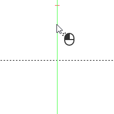
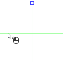
Straight construction lines may also be selected using the following automenu option:
|
<L> |
Select Line |
Upon activating this option, clicking ![]() anywhere in drawing select a nearest straight construction line.
anywhere in drawing select a nearest straight construction line.
Upon selecting a second source object, regardless of the method of selection, the preview of the dimension appears, while dimension line and value positioning, dimension symbol, dimension linking options and common options of 2D elements creation commands become available in the automenu. Dimension line will follow the cursor along the selected lines, and dimension value will follow the cursor along the dimension line. Witness lines will connect the dimension line with points of measurement on source objects.
When a graphic line segment is used a source object (no matter, first or second), the point of measurement is the endpoint of such segment nearest to the another source object.
When a construction line is used as the first source object, then the point of measurement is always the 2D node laying on the selected line. If there are multiple nodes on the line, then the one nearest to the point of clicking ![]() during line's selection is used as the point of measurement. If there are no nodes on the line, then such line cannot be selected as the first source object.
during line's selection is used as the point of measurement. If there are no nodes on the line, then such line cannot be selected as the first source object.
When a construction line is used as the second source object, the point of measurement might be one of the following:
•the nearest 2D node laying on the selected line (same as when selecting the first object), if there are 2D nodes on the line;
•the point of intersection between the line and the first source object, if there are no nodes on the line and the first source object is another construction line.
•the automatically defined arbitrary point on the line, if there are no nodes on the line and the first source object is a segment.
Intersecting lines split the plane into quarters. By default, the dimension is based on the quarter, through which the shortest path passes between the points, where the cursor was at the time of selecting the lines. Depending on the cursor position (inside or outside the selected quarter), the dimension either shows the angle of the selected quarter, or the total angle of the remaining three quarters.
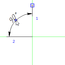
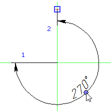
If necessary, you can select another quarter using the following automenu option:
|
<Z> |
Change Dimension Orientation (for angular dimension) |
Clicks ![]() on the icon of this option in the automenu sequentially switch the dimension between all possible quarters.
on the icon of this option in the automenu sequentially switch the dimension between all possible quarters.
Pressing the hotkey of this option selects the quarter, where the cursor is currently located. If the cursor is outside drawing window, the hotkey doesn't work.
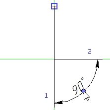
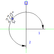
Set the desired positions of dimension line and value by moving the cursor, and confirm it by pressing ![]() or <Enter>. The dimension will be created. Upon creating a dimension, the command returns to initial state.
or <Enter>. The dimension will be created. Upon creating a dimension, the command returns to initial state.