Distance between Two Parallel Straight Lines or Line and Point |
  
|
In order to create a dimension representing distance between two parallel straight lines or between a straight line and a point, upon calling the ![]() Dimension command, select two source objects by clicking them with
Dimension command, select two source objects by clicking them with ![]() in any order. Construction and graphic lines are both available for selection. When selecting a construction line as first object, you can only select lines, which have at least one 2D node on them. When selecting second object, it doesn't matter, if the line has nodes or not. Characteristic points of graphic lines, 2D nodes and intersections of construction lines can be selected as points. Selecting an intersection of construction lines results in automatic creation of a connected 2D node there.
in any order. Construction and graphic lines are both available for selection. When selecting a construction line as first object, you can only select lines, which have at least one 2D node on them. When selecting second object, it doesn't matter, if the line has nodes or not. Characteristic points of graphic lines, 2D nodes and intersections of construction lines can be selected as points. Selecting an intersection of construction lines results in automatic creation of a connected 2D node there.
Straight construction lines and 2D nodes may also be selected using the following automenu options:
|
<L> |
Select Line |
|
<N> |
Select Node |
Upon activating any of these options, clicking ![]() anywhere in drawing select a nearest object of the corresponding type.
anywhere in drawing select a nearest object of the corresponding type.
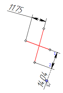
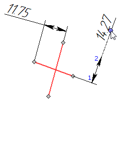
Upon selecting a second source object, regardless of the method of selection, the preview of the dimension appears, while dimension line and value positioning, dimension symbol, dimension linking options and common options of 2D elements creation commands become available in the automenu. Dimension line will follow the cursor in direction normal to the direction of measurement, and dimension value will follow the cursor along the dimension line. The direction of measurement is normal to the selected line. Witness lines will connect the dimension line with points of measurement on source objects. Set the desired positions of dimension line and value by moving the cursor, and confirm it by pressing ![]() or <Enter>. The dimension will be created. Upon creating a dimension, the command returns to initial state.
or <Enter>. The dimension will be created. Upon creating a dimension, the command returns to initial state.
Points of measurement on parallel lines and dimension's behavior in case of losing parallelism
When selecting a construction line as the first source object, the point of measurement is always the 2D node laying on the selected line. If there are multiple nodes on the line, then the one nearest to the point of clicking ![]() during line's selection is used as the point of measurement. If there are no nodes on the line, then such line cannot be selected as the first source object.
during line's selection is used as the point of measurement. If there are no nodes on the line, then such line cannot be selected as the first source object.
When selecting a construction line as the second source object, the point of measurement might be one of the following:
•the nearest 2D node laying on the selected line (same as when selecting the first object), if there are 2D nodes on it;
•the automatically defined arbitrary point on the line, if there are no 2D nodes on it.
Initially, when creating a dimension between construction lines, points of measurement only affect witness lines.
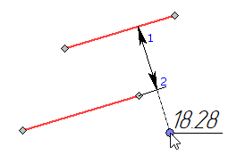
When selecting a segment as a source object, the point of measurement is its endpoint nearest to the dimension line. While the preview of the dimension gets dynamically updated depending on the cursor position, the point of measurement may automatically switch between segment's endpoints, depending on which endpoint is closer to the dimension line. At the moment of dimension's creation the point of measurement selection gets confirmed.
Initially, when creating a dimension between segments, points of measurement do not affect the result.
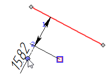
If, as a result of further editing of the drawing, lines/segments are no longer parallel to each other, then the dimension previously created between them starts indicating the distance between the first line/segment and the point of measurement on the second line/segment.
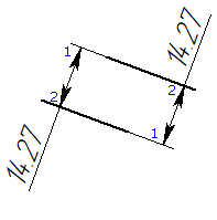
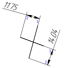
If a dimension was created between two parallel segments, or between a construction line and a graphic line segment parallel to the line, and later the parallelism was lost, then the point of measurement on the second segment can be switched by editing the dimension. During editing, the point of measurement on the second segment, and therefore the direction of measurement and dimension value, get automatically switched depending on, which endpoint of the segment is closer to the cursor. Besides, a witness line is drawn only for one of the endpoints.
