Arc Length between Two Nodes |
  
|
In order to create a dimension, representing a length of a circular arc's section limited by two 2D nodes laying on such arc, upon calling the ![]() Dimension command, activate the following automenu option:
Dimension command, activate the following automenu option:
|
<A> |
Arc Dimensions |
Activating this option sets selection filters in such way, that only circular arcs and points can be selected. Select two 2D nodes by clicking them with ![]() in any order.
in any order.
Alternatively, nodes may be selected using the following automenu option (after activating the previous one):
|
<N> |
Select Node |
Upon activating this option, clicking ![]() anywhere in the drawing results in selecting a 2D node nearest to the point of clicking.
anywhere in the drawing results in selecting a 2D node nearest to the point of clicking.
This option only allows to select existing 2D nodes. Without using this option, you may also select intersections of construction lines (upon selecting an intersection, a 2D node is automatically created there, and the dimension is based on such node).
Characteristic points of graphic lines are also available for selection, but a dimension of this type cannot be based on such points.
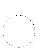
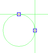
After selecting nodes, you should select a circle or a circular arc by clicking it with ![]() . The circle may be either construction or graphic line. If selected nodes lay on the selected circle/arc, then points of measurement will coincide with the nodes. If selected nodes do not lay on the selected circle/arc, then points of measurement will be defined as normal projections of the nodes onto the circle/arc.
. The circle may be either construction or graphic line. If selected nodes lay on the selected circle/arc, then points of measurement will coincide with the nodes. If selected nodes do not lay on the selected circle/arc, then points of measurement will be defined as normal projections of the nodes onto the circle/arc.
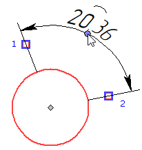
The preview of the dimension appears, while the dimension line and value positioning, dimension symbol, dimension linking options and common options of 2D elements creation commands appear in the automenu. Then the dimension line follows the cursor along witness lines, and the dimension value follows the cursor along the dimension line. Witness lines will connect the dimension line with the points of measurement. By default, witness lines are normal to the imaginary line, which is tangent to the arc and passes through arc's midpoint. In such case, the length of the dimension line is equal to the length of the selected arc section. If necessary, you can switch to another layout of witness lines, so that they'll be normal to the imaginary lines, which are tangent to the arc and pass through the selected nodes. In such case, the length of the dimension line will exceed the length of the selected arc section. Switching between witness lines layouts is performed using the following automenu option:
|
<H> |
Parallel/Radial Dimension Lines |
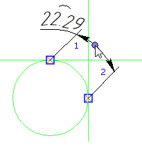
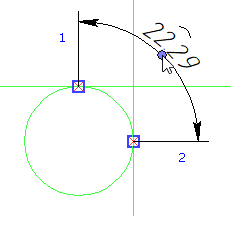
The direction of measurement depends on the position of the cursor in relation to the circular segment formed by the selected arc section and its radii passing through through the points of measurement. When the cursor is inside this segment or inside its extension formed by witness lines, the dimension value represents the length of the selected arc section. Otherwise, the dimension value represents the length of the rest of the circle, which forms the selected arc.

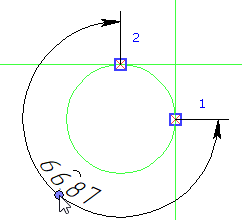
Set the desired positions of dimension line and value by moving the cursor, and confirm the input by pressing ![]() or <Enter>. The dimension will be created. Upon creating a dimension, the command stays in the arc dimensions creation mode.
or <Enter>. The dimension will be created. Upon creating a dimension, the command stays in the arc dimensions creation mode.
See Also: