Example of Custom Graphic Line Pattern |
  
|
Let's review custom line pattern creation on a simple example. We will create the line pattern shown on the figure:

1 - Tail, 2 - Line, 3 - Symbol, 4 - Space, 5 - Head
To create the pattern, let's create a new drawing.
Description of each line element shall be placed on a separate page of the document. For working convenience, each page can be renamed according to its purpose.
To create or rename document pages, use the Pages command .
When creating a line pattern, you can use sketch lines, as well as graphic lines snapped to construction lines. Lines can be of various types, colors and thickness.
We will begin creation of a line pattern from the Symbol. The points at which this element connects to its neighboring line pieces are marked by the named nodes, CenterStart and CenterEnd.
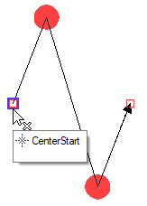
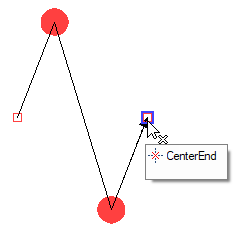
A name of a 2D element can be defined using the ![]() Element Name command available in element's contextual menu. Alternatively, a node's name can be defined in the Edit Node command, a path's name – in the Edit Construction command, using the dedicated automenu option.
Element Name command available in element's contextual menu. Alternatively, a node's name can be defined in the Edit Node command, a path's name – in the Edit Construction command, using the dedicated automenu option.
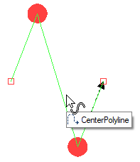
Next, we need to decide whether to prescribe the path for hatches. Suppose, this line may be used in the future for creating hatches, so that the hatch or fill contours should coincide with line elements. For this purpose, we will create a named path, CenterPolyline, starting and ending in the named nodes CenterStart and CenterEnd and coinciding with element's graphic lines.
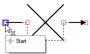
Next, we will draw the Space element. Nodes for attaching this element to adjacent segments of the line will be named Start and End. Let's also draw a hatch path for the Space and name it Polyline.
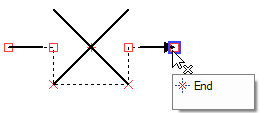
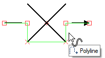
The Line element will consist of LineStart and LineEnd nodes connected by the straight graphic line.


Similarly, we will create descriptions of the tail and head of the line on separate pages, as shown on the figure. We will have to use a hatch to create the filling. No additional paths for hatches will be created. In this case, the contour of a hatch bounded by this line type will go straight between the border nodes of these line elements.
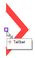
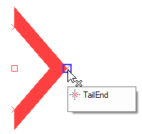
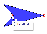
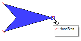
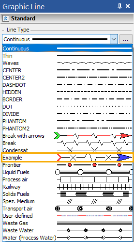
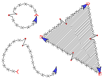
What is left to do before using the created template is to save it in the LinePatterns folder under the Example name and restart T-FLEX CAD. After restarting, the new line with this name will appear in the list of line types. It can be used just like a standard line type.
See Also: