Outline of Hatch Contours |
  
|
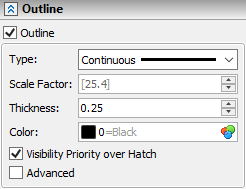
By default, lines of hatch contours are not displayed in drawing, in order to avoid duplication in cases, where hatch contour is based on graphic lines. If you lines of hatch contours to be displayed, enable the Outline checkbox in the eponymous tab of the ![]() Hatch command's parameters window. It can be helpful, when a contour is based on 2D nodes and construction lines. Below the checkbox you can set following outline parameters:
Hatch command's parameters window. It can be helpful, when a contour is based on 2D nodes and construction lines. Below the checkbox you can set following outline parameters:
Type
Type of contour lines. Outline may use same line types as graphic lines. The drop-down list of this parameter contains line types described in the tcad.lin file and line types based on custom patterns.
Scale Factor
Scale factor of line's dashes. It doesn't affect continuous line types. Default value is displayed in square brackets, which means that it's defined by document parameters (Document Parameters > Page > Lines > Line Style > Scale factor for dashed lines).
Thickness
Thickness of lines applied to line types described using a *.lin-file. Default value is displayed in square brackets, which means that it's defined by document parameters: for Continuous type it is defined by the Thick Lines parameter, for other types - by the Other Lines parameter (Document Parameters > Page > Lines > Lines). The Thin line type always inherits thickness from document parameters, regardless of whether the user have inputted a custom value in hatch parameters. Line types described using a *.grb-file always inherit thickness from such file.
Color
Color of outline can be selected from the drop-down list, defined via a numerical value or selected from the catalog.
Visibility Priority over Hatch
By default, thickness of the outline is applied symmetrically. So half of the outline thickness interferes with the contour filling. If this checkbox is enabled, the outline overlaps the filling and vice versa.

Advanced
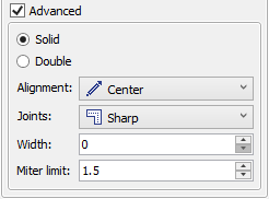
Enabling this checkbox invokes additional parameters of the outline:
•Solid/Double
You can switch between a single and a double outline.

•Alighnment
Method of Thickness application. Following methods are available:
![]() Center
Center
Thickness is applied symmetrically.

![]() Left
Left
Thickness is applied to the left in relation to the contour direction.

![]() Right
Right
Thickness is applied to the right in relation to the contour direction.

•Joints
Type of contour lines' joints at contour angles. Following options are available:
![]() Round
Round
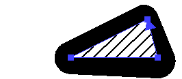
Angles are rounded. Rounding radius depends on thickness and width.
![]() Sharp
Sharp
Angles are not modified.
![]() Mitered
Mitered
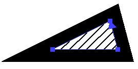
Angles are cut by a straight line normal to bisector at at a distance defined by the Miter limit (see below).
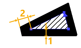
1 - Width; 2 - Miter limit
•Width
When using a single outline, this parameters defines the line thickness. In such case the Thickness parameter has no effect.
When using a double outline, this parameter defines distance between parallel lines forming of the double outline.
•Miter limit
Distance at which angles are cut, when using the mitered joints (see above). This parameter doesn't affect joins of other types.