Style of Roughness |
  
|
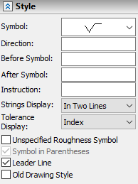
The Style tab of the ![]() Roughness command's parameters window contains following parameters
Roughness command's parameters window contains following parameters

Symbol
Type of roughness symbol can be selected in the drop-down list:

Direction
Direction of surface irregularities is specified by a symbol in front of values of roughness parameters within the roughness symbol. Direction symbol can be typed in via keyboard or inserted from the special symbols library using the Insert Symbol <Alt>+<F9> command, which is available in the contextual menu of the input box.

Before symbol
Text string to be displayed to the left of the roughness symbol.
After Symbol
Text string to be displayed to the right of the roughness symbol.
Instruction
Text string to be displayed above of the roughness symbol.
When inputting text strings, you can use text variables by inputting their names in curvy braces and utilize the commands available in contextual menu of input boxes.
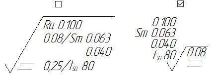
Display format of roughness parameters expressed by combination of minimal and maximal value. You can select one of the following options in the drop-down list:
•In Two Lines

•Index
![]()
•Fraction

Display format of limit deviations of roughness parameters expressed by nominal value and deviations. You can select one of the following options in the drop-down list:
•On One Line
![]()
•Index
![]()
•Fraction

Symmetric deviations are always displayed on one line, regardless of the selected option.
![]()
Unspecified Roughness Symbol
The size of the roughness symbol depends on the font size set in the Font tab of the roughness parameters dialog. By default, designations of roughness for particular surfaces use the 5 mm or 0.25 in font size. Enabling this checkbox set the font size to 7 mm for ISO drawings, which corresponds to the unspecified roughness designation. For ANSI drawings it is recommended to input font size of unspecified roughness manually. This checkbox is disabled by default for the ![]() Roughness command and enabled by default for the
Roughness command and enabled by default for the ![]() New Unspecified Roughness command.
New Unspecified Roughness command.
Symbol in Parentheses
This checkbox is available, only if the Unspecified Roughness Symbol checkbox is enabled. It controls the display of the special symbol, which is shown in parentheses for the unspecified roughness designation.

Leader Line
This checkbox controls the display of the witness line. Witness line may be displayed, when snapping a roughness designation to a straight graphic line segment or to a straight construction line. In the first case, it connects the designation with the nearest endpoint of the segment; in second case, it connects the designation with the nearest 2D node laying on the selected line.

Old Drawing Style
This checkbox enables the old display format of roughness designation.
