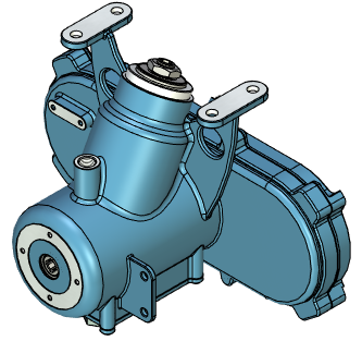
3D Section by 3D Points |
  
|
3D section can be created by by 3D points using the following option available in the ![]() 3D Section command's parameters window:
3D Section command's parameters window:
|
Construct Section using 3D View |
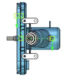
A section of this type cuts-off portion of a model located by one side of a specified set of connected planes. In order to define cutting planes, you need to select a sequence of 3D points (3D nodes or vertices of bodies). The selected 3D points are joined by straight line segments. Cutting planes are constructed by extruding the resulting polyline in the direction normal to the screen.
Before creating a section, you need to set an active camera in the 3D scene in such way, that the desired direction of extruding the cutting planes is normal to the screen. This can be done, by applying one of the standard view points or by specifying a desired view point in 3D View Parameters. If the section has to be normal to some face or flat edge of the model, you can use the command Rotate Normal to Selected Element. The direction of extruding the polyline is defined at the time of selecting the first point, so you can rotate the camera freely, when selecting other points.
A length of the extrusion is defined arbitrarily by the system. It is used only for displaying the section in the 3D scene and doesn't affect the result of applying the section. When applying the section, infinite cutting planes are used.


3D points can be selected using the following options:
|
<N> |
Select 3D node |
|
<V> |
Select Vertex |
Activating these options enables in the Filter Toolbar filters for selecting objects of the corresponding type, so you can select desired points in 3D scene or in model tree via ![]() .
.
You should select at least two points. Maximum number of points is not limited. Selected points are connected in the order of their selection. So, if some point was missed, you have to clear the selection and re-select all points. The following option clears the selection:
|
<K> |
Eliminate all Section Nodes |
Default view direction is defined by the system arbitrarily. If necessary, you can change the direction using the following option:
|
<D> |
Switch view direction |
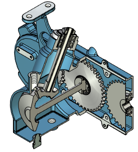
Upon applying the section, the portion of the model pointed by section's arrows will remain visible, while the other portion will be omitted.
See Also: