Custom Pipeline Middle Fragments |
  
|
Examples of standard middle segments of pipelines, wires/cables and air ducts are supplied with T-FLEX CAD. You can use them in the ![]() Pipeline, Wire/Cable, Air Pipe command. If necessary, you can create a custom library of middle segments for any type of routings. When creating fragments for such library, follow the rules described below.
Pipeline, Wire/Cable, Air Pipe command. If necessary, you can create a custom library of middle segments for any type of routings. When creating fragments for such library, follow the rules described below.
In the fragment file you must create the following external variables and use them for defining corresponding geometrical parameters:
•Diameter or D - pipe diameter (permissible values range from 0 to 10000)
•Thickness or T - pipe wall thickness (permissible values range from 0 to 10000)-
•InnerDiameter or InnerD – flag for usage of internal diameter (possible values 0 or 1)
Variable InnerDiameter (InnerD) can be used for the suppression of one of the bodies in the fragment file. One body will be visible when using internal diameter, another - using external.
To create a 3D model of the middle of the pipe, you can use any convenient operation, such as Sweep. It is important that the body is based on a 3D curve.
After creating 3D model, you should do the following:
•Set parameters listed below in the Adaptive Fragment command. This will create a pipeline using any selected route.

oName.
The name of operation, which will be assigned to the pipe using this fragment.
oGeometrical parameters:
▪Trajectory (3D curve or route). Element that defines the trajectory of the pipeline.
▪pipe start 3D node
▪pipe end 3D node
It is important to comply with the order of geometrical parameters in the list. The first must be trajectory, and then the start and end points.
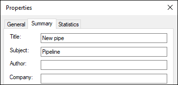
•Specify the name that appears in the list of pipeline middle types in the pipeline creation command using the ![]() Properties command.
Properties command.

•Create custom external variables dialog (optional step). This dialog is automatically embedded in the parameters window when you call editing of ending variables in the command of pipeline creation/editing.
Learn how to create a dialog in the Controls chapter.
•Create icon using the Icon command (optional step).
•In the variable editor add diagnostics for invalid combinations of fragment's external variables values.
•Save the fragment document.
•Add the fragment into the standard pipeline segments library using the following automenu option of the ![]() Pipeline, Wire/Cable, Air Pipe command
Pipeline, Wire/Cable, Air Pipe command