Pipeline, Wire/Cable, Air Pipe |
  
|
3D geometry of pipelines, wires/cables, air pipes is created using the same command in different modes. The modes differ in types of connection points, routes and fittings available for selection.
For example, air ducts can be built only on the corresponding type of routes, and connected only to other air pipes. This is done to eliminate errors in cases where there are several types of communications in the assembly at once.
Elements without an assigned type can be connected to any communications, including fittings.
Detailed information about setting communication types can be found in the section Routing Connection Types.
To create communications without an assigned type, use the following command:
Icon |
Ribbon |
|---|---|
|
3D Model > Create > Pipeline |
Keyboard |
Textual Menu |
<3PI> |
Operation > Pipeline |
The command includes elements of beginnings, endings and connections from different types of routings.
In order to create a routing of a particular type, the same command may be called within corresponding mode:
•within the ![]() Pipeline mode:
Pipeline mode:
Icon |
Ribbon |
|---|---|
|
Routing > Pipeline |
Keyboard |
Textual Menu |
|
Tools > Routing > Pipeline > Pipeline |
•within the ![]() Electricity mode:
Electricity mode:
Icon |
Ribbon |
|---|---|
|
Routing > Wire, Cable |
Keyboard |
Textual Menu |
|
Tools > Routing > Electricity > Wire, Cable |
•within the ![]() Ventilation mode:
Ventilation mode:
Icon |
Ribbon |
|---|---|
|
Routing > Air Pipe |
Keyboard |
Textual Menu |
|
Tools > Routing > Ventilation > Air Pipe |
The following section provides a general description of the functionality of commands without dividing into communication types. Regardless of the selected mode, the resulting operation is called ![]() Pipe.
Pipe.
For working with pipelines, the type of product composition is the Pipeline Table.
Route creation example
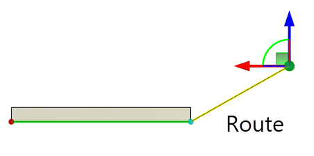
This section provides a general case of creating a pipeline type of routing. First you have to create its trajectory using the ![]() Route command. Alternatively, trajectory may be defined using a model edge or any other wire-frame element.
Route command. Alternatively, trajectory may be defined using a model edge or any other wire-frame element.

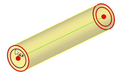
The pipe profile shape and dimensions are specified without additional constructions. They are set in the parameters window after the command activation.
You can create a pipe along the whole route or its part.

To define the operation, follow the steps:
1.Select 3D curve defining the trajectory.
2.Select starting and ending points of the pipe (optional).
3.Define operation parameters (pipe diameter, wall thickness, etc.).
4.Confirm operation creation ![]() <Ctrl>+<Enter>.
<Ctrl>+<Enter>.
Topics in this section:
•General Parameters of Pipeline
•Shape of Pipeline Cross-Section