LCS Parameters |
  
|
Parameters of an LCS are defined in the dialog box invoked by the option:
|
<P> |
Set entity parameters |
Some parameters of this dialog are common across all 3D elements. Their detailed description is provided in the chapter General parameters of 3D elements.
Other parameters of the given dialog duplicate parameters of the LCS parameters window already described above. Thus, only those LCS parameters which were not mentioned in the previous section of this chapter will be described in this section.
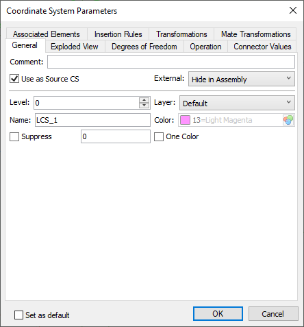
You can define the following parameters of an LCS on the tab General:
•Comment. This parameter allows specifying a text string – the description of the given LCS. The comment helps selecting a coordinate system from the list of those available for positioning, when applying a 3D fragment.

•Use One Color. This flag is responsible for the LCS viewing colors. When it is turned off, the LCS axes are drawn with different colors. Each axis color (red, green, or blue) corresponds to the color of the global axis. When the flag is turned on, the LCS is drawn with one color (Color parameter).
Display of LCS by |
|
•Use as Source CS. Allows you to use this LCS as the source CS of fragment, when inserting the current document into an assembly.
•External. Adjusts visibility in the assembly (see Visibility of LCS in Assembly).
•Level. The value of the visibility level.
•Layer. The name of the layer that the coordinate system belongs to.
•Color. The color with which the LCS is drawn in the 3D window.
•Name. By default, the following names are generated ("LCS_1", "LCS_2", etc.).
•Set as default. The selected option means that the specified general parameters will be used for all subsequent operations.
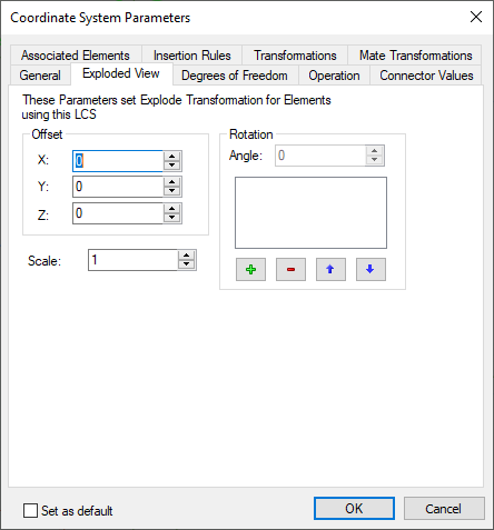
On the tab Exploded View, you can specify the transformations that will be applied to 3D fragments attached to the given LCS in the exploding mode (the command Tools > Exploded View).
