3D Node on Path |
  
|
The command can be called in one of the following ways:
Icon |
Ribbon |
|
Support Geometry > 3D Node > 3D Node on Path |
Keyboard |
Textual Menu |
<3KNP> |
|
Automenu of the |
|
<P> |
On Path |
This method involves creating a 3D node on elements of wire geometry. These elements include edges, 3D profiles, 3D paths and routes.
Upon calling the command, filter for selecting wire-frame elements ![]() becomes active in the filters toolbar. Select
becomes active in the filters toolbar. Select ![]() in 3D scene or in model tree a source element to be used for 3D node's creation. Selected element may be either open or closed.
in 3D scene or in model tree a source element to be used for 3D node's creation. Selected element may be either open or closed.
Upon selecting a source element, coordinates' input boxes appear in the Coordinates tab of the parameters window and coordinates' manipulators appear in the 3D scene.
Position of a node is defined by following cylindrical coordinates:
•U - the position of the node or its normal projection on the source element relative to a reference point;
depending on the selected Coordinates Type it is measured either in absolute length units or in fractions of source element's length;
•V - angle of rotating the node around source element where the center of rotation is defined by the U coordinate and the radius is defined by the R coordinate;
•R (radius) - offset from the source element in normal direction at the point defined by the U coordinate, where the direction of offset is defined by the V coordinate.
By default, a node is created directly on the source element without offset (R = 0), and the initial value of the U coordinate corresponds to the cursor's position at the moment of selecting the source element.
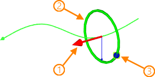
1 - manipulator of the coordinate U;
2 - manipulator of the radius R;
3 - manipulator of the angle of rotation V.
In order to change coordinates using manipulators, move the cursor over the manipulator of desired coordinate and click it ![]() . The manipulator, as well as the position of the node in corresponding direction, will start following the cursor. Set the desired position of the node and click
. The manipulator, as well as the position of the node in corresponding direction, will start following the cursor. Set the desired position of the node and click ![]() again to confirm changes.
again to confirm changes.
The Coordinates type drop-down list contains following options:
![]() By Offset
By Offset
The U coordinate is measured in absolute length units;
![]() Parametric
Parametric
The U coordinate is measured in fractions of source element's length, from 0 to 1.
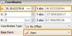
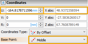
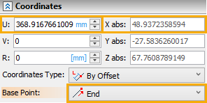
Same position of the node defined using different base points
The origin of the U coordinate can be selected in the Base Point drop-down list:
![]() Start
Start
The U coordinate is measured from the starting point of the source element.
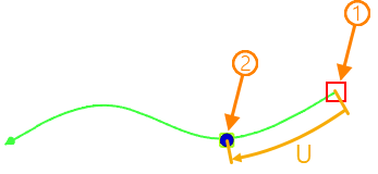
1 – Base Point; 2 – Created 3D Node
![]() Middle
Middle
The U coordinate is measured from the middle point of the source element.
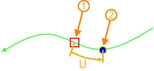
1 – Base Point; 2 – Created 3D Node
![]() End
End
The U coordinate is measured from the ending point of the source element.
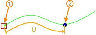
1 – Base Point; 2 – Created 3D Node
Moreover, you can select an arbitrary base point. Upon selecting a source element, the filter for selecting points ![]() becomes active in the filters toolbar in addition to the initially active filter for selecting wire-frame elements. Then you can select
becomes active in the filters toolbar in addition to the initially active filter for selecting wire-frame elements. Then you can select ![]() in the 3D scene or in the model tree either a new source element, which will replace the current one, or an arbitrary point. If selected point belongs to the source element, it becomes the new base point for U coordinate; if selected point doesn't belong to the source element, its normal projection onto the source element becomes the new base point.
in the 3D scene or in the model tree either a new source element, which will replace the current one, or an arbitrary point. If selected point belongs to the source element, it becomes the new base point for U coordinate; if selected point doesn't belong to the source element, its normal projection onto the source element becomes the new base point.
Alternatively, in order to select an arbitrary base point, click ![]() the U coordinate's manipulator, then select the Position on Nearest Point option in the appeared contextual menu. Upon selecting this option, only the points
the U coordinate's manipulator, then select the Position on Nearest Point option in the appeared contextual menu. Upon selecting this option, only the points ![]() selection filter remains on the filters toolbar
selection filter remains on the filters toolbar
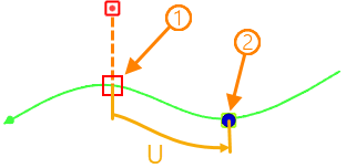
1 – Base Point; 2 – Created 3D Node
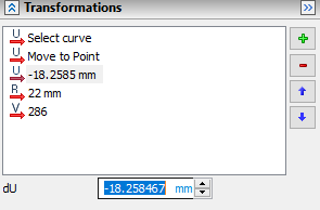
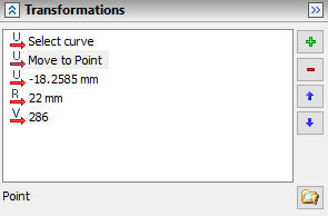
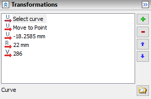
Changes in 3D node's position are displayed in the Transformations tab of the parameters window. This tab works in the same way as described for Transformations of 3D elements.
When changing the base point, the position of the 3D node remains the same, while the value of the U coordinate is recalculated in relation to the new base point.
If Start or Middle option is selected in the Base Point drop-down list, then the direction from starting to ending point of the source element is considered as positive direction of the U coordinate. If End option is selected, then the direction from ending to starting point is considered as positive. This rule also works for arbitrary base points: in such case the option selected in the Base Point drop-down list doesn't define the position of the base point, but still defines the direction.