Sketch > Slot |
  
|
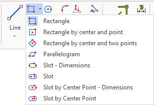
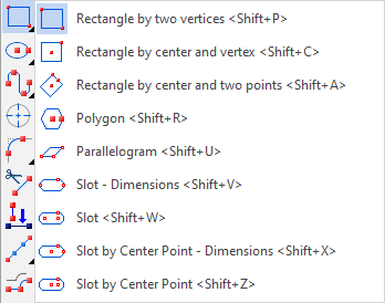
In the ribbon, as well as in the automenu of the Sketch command, the slot creation options are grouped in the same drop-down list as rectangles, polygon and parallelogram creation options. The presence of the drop-down list is indicated by the black triangle near an icon of an option displayed, when the list is folded. In order to unfold the list, either click ![]() a triangle
a triangle ![]() in the ribbon, or click and hold
in the ribbon, or click and hold ![]() on an icon of an option displayed, when the list is folded. This icon corresponds to an option used last in the current CAD session. When the Sketch command is launched, any option can be called via keyboard without unfolding the list.
on an icon of an option displayed, when the list is folded. This icon corresponds to an option used last in the current CAD session. When the Sketch command is launched, any option can be called via keyboard without unfolding the list.
Moreover, upon calling any of the slot creation options, you can switch between different types of slots using buttons located in the parameters window.
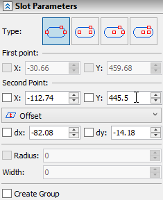
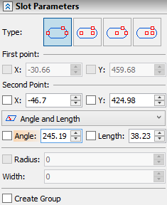
Also the parameters window contains slot parameters.
Slot of all types have the same set of parameters.
The creation of a slot begins with specifying the first point. You can do this either in absolute coordinates, or snap a node to any object.
The second point can be set in a variety of ways. Similarly to the first point, you can snap it to any object or set coordinates. Additionally, you can select a construction option: Offset or Angle and Length.
If you select the Offset option, you must specify the dx and dy offsets along the coordinate axes relative to the first point.
Angle and Length let you set the angle of rotation of the centerline and the distance between the first and second point.
After the points have been specified, you can set the width of the groove and the radius of the circles.
When inputting values of parameters, you can use hot keys and checkboxes fixing values.
There is the Create Group checkbox at the bottom of the parameters window. When it's enabled, lines forming each created slot will be united into a separate group.
Icon |
Ribbon |
|---|---|
|
Draw > Sketch > Rectangle > Slot - Dimensions Remarks > Remarks > Line > Slot - Dimensions Workplane > Sketch > Rectangle > Slot - Dimensions |
Keyboard |
Textual Menu |
<SK>> |
|
Automenu of the |
|
<Shift>+<V> |
Slot - Dimensions |
When constructing a slot in this way, the first and second points will be the overall dimension of the slot length.
Icon |
Ribbon |
|---|---|
|
Draw > Sketch > Rectangle > Slot Remarks > Remarks > Line > Slot Workplane > Sketch > Rectangle > Slot |
Keyboard |
Textual Menu |
<SK>> |
|
Automenu of the |
|
<Shift>+<W> |
Slot |
The first and second points of this type of slot are the centers of the slot circles.

Slot by center point - Dimensions
Icon |
Ribbon |
|---|---|
|
Draw > Sketch > Rectangle > Slot by center point - Dimensions Remarks > Remarks > Line > Slot by center point - Dimensions Workplane > Sketch > Rectangle > Slot by center point - Dimensions |
Keyboard |
Textual Menu |
<SK>> |
|
Automenu of the |
|
<Shift>+<X> |
Slot by center point - Dimensions |
In this case, the first point is the center of the groove, and the second defines the dimension of the slot length.

Icon |
Ribbon |
|---|---|
|
Draw > Sketch > Rectangle > Slot by center point Workplane > Sketch > Rectangle > Slot by center point |
Keyboard |
Textual Menu |
<SK>> |
|
Automenu of the |
|
<Shift>+<Z> |
Slot by center point |
Similar to the previous version, the first point is the center of the groove, while the second point is the center of the circle.
