Example of Parametric Symbol Creation |
  
|
Many of the fonts available in T-FLEX CAD contain the integral symbol. When using such symbol, the limits of integration should be added either as upper and lower indexes (which yields a result slightly different from the limits placement common in English typography tradition), or as separate text objects manually positioned in relation to the integral symbol (which allows to achieve any desired placement, but isn't convenient). In this example we will create an integral symbol, which allows to set limits in symbol's parameters dialog. We'll also add the ability to select number of nested symbols for multiple integrals designation. The result will comply with German typography tradition, where the integral symbol is usually upright and the limits are placed above and below it. However, you can create you own layout, using the same algorithm with different limits placement and font style options.
First, open a new ISO drawing and create two variables. The external numeric variable mult will define number of nested symbols, taking whole values from 1 to 4. For now, let's set its value to 1 (values switch will be added later). Textual variable $sign will contain the required number of integral symbols depending in the value of the mult variable. This will be achieved by using the switch(,,) function in the expression of the $sign variable. The first argument of the function is the name of the mult variable; it is followed by possible values of the mult variable (1, 2, 3, 4) paired with corresponding values of the $sign variable ("∫", "∫∫", "∫∫∫", "∫∫∫∫"). You can copy the integral symbol from the help into the system clipboard and then paste it into the expression.

Then call the ![]() Text command and select the
Text command and select the ![]() string text creation option. In order to use the LCS origin of the current page as the anchor point of the text, point it with the cursor and press
string text creation option. In order to use the LCS origin of the current page as the anchor point of the text, point it with the cursor and press ![]() . The text parameters dialog will appear. Type {$sign} into the input box of the Contents tab, so the text will contain value of the $sign variable.
. The text parameters dialog will appear. Type {$sign} into the input box of the Contents tab, so the text will contain value of the $sign variable.

The default font applied to the text doesn't contain integral symbol, so we have to select a different font (T-FLEX STANDARD) in the Font tab of the same dialog.
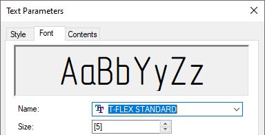
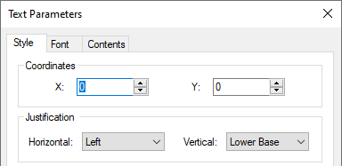
Then, switch to the Style tab and input zero coordinates X and Y of the anchor point. Also select the Lower Base option for the vertical justification. Press OK to finish the text creation.
Now we need the ID of the created text. Call the ![]() Information command from the contextual menu of the text and copy the ID into clipboard.
Information command from the contextual menu of the text and copy the ID into clipboard.
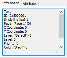
Create the numeric variable x and make it equal to the width of the text using the get(,) function. The first argument of the function is the ID of the text, the second argument is the name of the desired dimension (WIDTH).

Now we should synchronize the size of the symbol with the size of its page, in order to ensure correct scaling of the symbol in accordance with the target font size, when inserting the symbol into texts. The left boundary of the page already coincides with the left edge of the text, as well as the bottom boundary of the page coincides with the lower baseline of text's font (the symbol itself is slightly extended beyond the upper and lower baselines of the font). So we only need to coincide the right boundary of the page with the right edge of the text and the top boundary of the page with the upper baseline of text's font. To do so, create two variables - top and right, and set coordinates of page boundaries using the setv(,) function in the expression of these variables. The first argument of the function is the name of the corresponding service parameter (XH is the X coordinate of the right boundary of the page, YH is the Y coordinate of the top boundary of the page) combined with the name of the desired page (in our case the name of the page remains default - Page 1). The second argument of the function for the right boundary is the name of the x variable, for the top boundary - number 5 (because the symbol have the default font size equal to 5).

Next, we will add limits of integration. Create two external textual variables $a (lower limit) and $b (upper limit). For now, let's set their values to "a" and "b" (values input boxes will be created in the external variables dialog later).

Create a new string text, which will be the lower limit of integration. Type {$a} into the input box of the Contents tab of text parameters dialog, so the text will contain value of the $a variable.

Then switch to the Font tab of the same dialog and set the font size to 2.5.
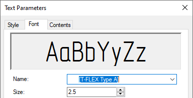
Finally, in the Style tab select the Center option for the horizontal justification and set the X coordinate to x/2, so the lower limit will always be below the center of integral symbols, regardless of their quantity. Vertical justification and Y coordinate can be set to you liking, or you may use the parameters shown below.
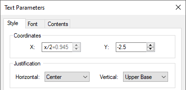
Press OK to finish lower limit creation. Then create another string text, which will be the upper limit of integration. Type {$b} into the input box of the Contents tab of new text parameters dialog.

Same as before, set the font size to 2.5 in the Font tab

In the Style tab select the Center option for the horizontal justification and set the X coordinate to x/2, so the upper limit will always be above the center of integral symbols, regardless of their quantity. Vertical justification and Y coordinate can be set to you liking, or you may use the parameters shown below.
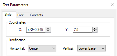
Press OK to finish upper limit creation. In result, the drawing looks like this:

Now call the ![]() Pages command and add a new page of the
Pages command and add a new page of the ![]() Control type. Then, call the
Control type. Then, call the ![]() Control command and add to the created page two
Control command and add to the created page two ![]() Edit Boxes for $a and $b variables, and four
Edit Boxes for $a and $b variables, and four ![]() Radio Buttons for the mult variable. In parameters of radio buttons, set variable values to 1, 2, 3 and 4 and add similar captions.
Radio Buttons for the mult variable. In parameters of radio buttons, set variable values to 1, 2, 3 and 4 and add similar captions.
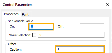
Set the layout of the control page and add static texts, as you see fit. In result, the page should look something like this:
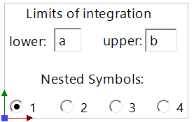
Now we name the integral drawing Integral.grb and save it into a separate folder. Then open a new ISO drawing and create a string text. When inputting the text content, invoke the symbols insertion dialog (<Alt>+<F9>). In the symbols insertion dialog press the Add... button. The file selection dialog of the operating system appears, where we should select the folder containing the integral drawing. In result, the folder will appear in the catalog in the left section of the symbols insertion dialog. Select it with ![]() , then select the integral symbol in the right section of the dialog.
, then select the integral symbol in the right section of the dialog.
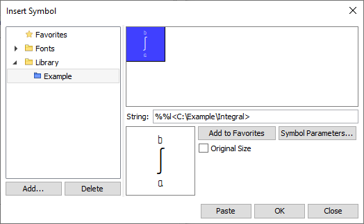
Press the Symbol Parameters... button, in order to invoke the external variables dialog. In the external variables dialog set desired limits of integration and number of nested signs OK.
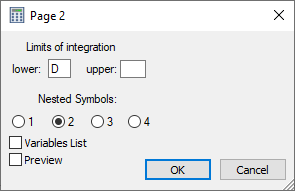
In the symbols insertion dialog the preview of the integral and the content of the String box will be changed in accordance with specified parameters.
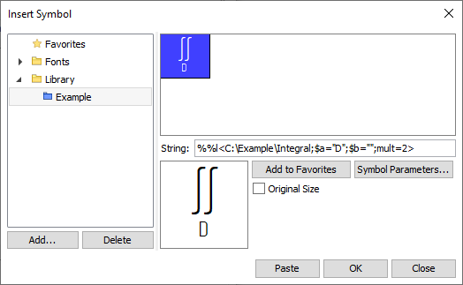
Press OK to insert the symbol. the code of the symbol will appear in the text content input box. If you activate the textual cursor in this box, the preview of the resulting text with applied formatting will appear above the box. Add an arbitrary string after the symbol and press OK to finish text creation.

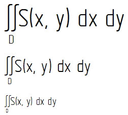
The created text looks like this:

Changing text font size results in similar changes of symbol size:
See Also: