Parameters Dialog of Operations and Bodies > Common Parameters |
  
|
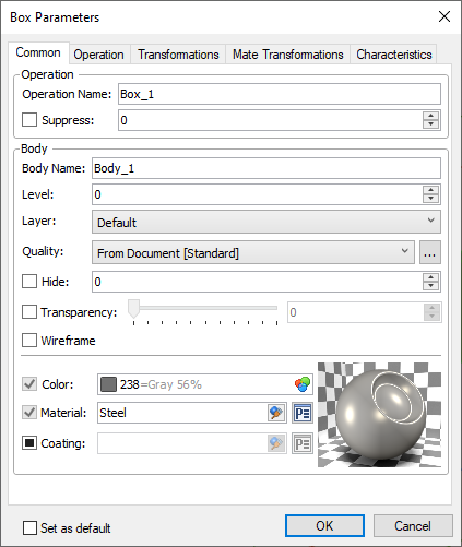
Each 3D operation's parameters dialog contains the similar tab - Common. It contains non-specific parameters of an operation and parameters of a body formed or modified by this operation. Body parameters are common for all operations belonging to this body's tree. If you invoke a parameters dialog for a body itself, a parameters of a last operation in this body's tree are displayed.
If you invoke an array's parameters dialog from the Operations > Arrays folder in the model tree, displayed body's parameters (except name) are applied to all bodies created by this array. In this case Body Name input box contains a random value, which isn't applied to anything.
The content of the tab is split into following groups

The group contains following parameters:
Operation Name
3D operations as well as other 3D elements have a unique name. User can type name manually. In this case the system checks if typed name is unique. If typed name is already assigned to another element in this document, the changes are not applied. If user didn't input a custom name, the system generates name automatically. More information about automatically generated names can be found in the Names Customization for 3D Elements chapter.
Suppress
This option can be used for excluding a particular operation from the 3D model generation. Suppressed operation isn't displayed in the 3D scene. It might be useful when working on complex assemblies. Suppress the element that you're not interested in at the moment so that they don't block the view. Enabling the Suppress checkbox excludes an operation from the model generation and sets the "1" value in the corresponding input box. Disabling the checkbox includes an operation into the model generation and sets the "0" value in the corresponding input box. Value may also be typed manually or defined by a real variable for controlling the suppression via Parametrization. An operation is suppressed if a variable's value isn't zero. Any whole values apart from zero are replaced by "1". Fractional values are not allowed.
Keep in mind, that suppression of a parent operation leads to errors upon regenerating its child operations.
The group contains following parameters:
Body Name
It's a name of body formed or modified by the selected operation. Body name works in the same way as described for operation name above.
Level
This parameter is described in the Levels chapter.
Layer
This parameter is described in the Layers chapter.
You can adjust the quality of displaying the particular body in the 3D window. The drop-down contains options similar to described in the Image Quality chapter. The additional From fragment option is available for 3D fragments. It uses the quality parameters from the fragment's document parameters.
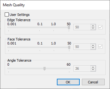
If you want to use one of the system presets as a template for customizing user-defined parameters, select a preset in the drop-down and click the ![]() button located to the right side of the drop-down. The Mesh Quality dialog will appear with parameters of a selected preset. Enable the User Settings checkbox to edit them.
button located to the right side of the drop-down. The Mesh Quality dialog will appear with parameters of a selected preset. Enable the User Settings checkbox to edit them.


Transparency
If you want to make a body transparent, enable this checkbox and use the slider or the input box for adjusting the transparency level.
Wireframe
Enabling this checkbox applies the Wireframe view style to this body independently of the style selected for the whole window.
Hide
This option allows to disable displaying of a body without excluding it from the model generation.
The group contains following parameters:

Bodies created by most of 3D modeling operations have parameters of this group assigned individually.
Color and Material are assigned by default upon creating a body. They couldn't be deleted, but could be edited. That's why the corresponding checkboxes are enabled and inactive.
Coating is not assigned by default.
Bodies created from other bodies by such operations as Copy, 3D Symmetry, Array and Divide inherit such parameters from the source body. 3D Fragments inherit such parameters from the fragment's document. In these cases the input box of an inherited parameter is inactive and contains either [Source operation] or [From fragment] value, while the corresponding checkbox is disabled. Enable the checkbox to define a parameter manually.


Color
This is a color of a body in all view styles except Render. Color here can be selected in the same way as described in the Color chapter.
Material
This parameter defines the material of a body. It is used for mass-inertia parameters calculation and engineering analysis. It is also used visualization of a body in the 3D scene in the Render style, if no coating is assigned.
The input box contains a name of a currently assigned material. If you need to assign another material, click the ![]() Select Material button in the right side of the input box. A drop-down window appears. It is a simplified version of the
Select Material button in the right side of the input box. A drop-down window appears. It is a simplified version of the ![]() Materials tool window. Two tabs are available there: Document (contains the list of materials used in the current document) and Libraries (contains available material libraries). The search box is available in the upper part of the window. Type a search query and click the
Materials tool window. Two tabs are available there: Document (contains the list of materials used in the current document) and Libraries (contains available material libraries). The search box is available in the upper part of the window. Type a search query and click the ![]() Find Material button. The list of materials will be filtered according to the query.
Find Material button. The list of materials will be filtered according to the query.
Name is the only column in the materials list by default. Columns containing the material's physical characteristics could be enabled using the ![]() Selection of columns button located to the right side of the search box.
Selection of columns button located to the right side of the search box.

Select the desired material in the list using ![]() . The drop-down window will disappear and the selected material will be assigned to a body.
. The drop-down window will disappear and the selected material will be assigned to a body.
Coating
This is an additional material used for visualization only. Even if the coating is applied, mass-inertia parameters calculation and engineering analysis still use the main material. Enable the corresponding checkbox to apply coating. Coating material selection is performed in the same way as described for the main material.
If Material and Coating are not inherited, they are previewed in the right area of the dialog. Preview uses ball or cube sample with cutout. Click ![]() on the preview to switch between ball and cube.
on the preview to switch between ball and cube.


Clicking the ![]() button located to the right side of the corresponding input box invokes the Material Properties dialog.
button located to the right side of the corresponding input box invokes the Material Properties dialog.
Material and Coating may also be defined using a string variable. Detailed information about working with materials can be found in the Materials chapter.