3D Section by Parallelepiped |
  
|
3D section by parallelepiped angle can be created using the following option available in the ![]() 3D Section command's parameters window:
3D Section command's parameters window:
|
Create Section by Parallelepiped |
A section of this type cuts-off portion of a model located inside or outside the specified parallelepiped.
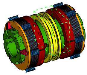
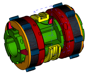
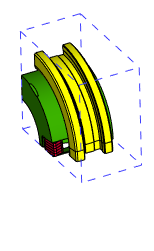
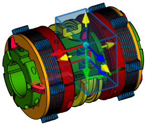
When creating a section by parallelepiped, position, dimensions and orientation of the parallelepiped, as well as view direction, are set using special manipulators.
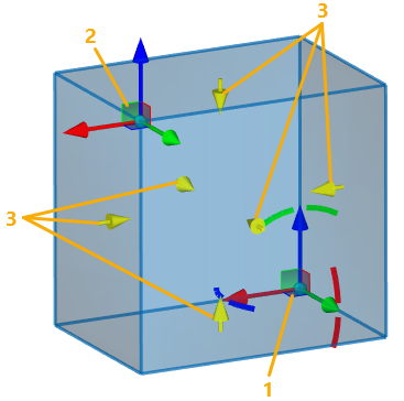
1 - LCS manipulator of parallelepiped's starting vertex
2 - LCS manipulator of parallelepiped's ending vertex
3 - View direction manipulators
Position, dimensions and orientation of parallelepiped
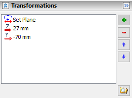
Position, dimensions and orientation of parallelepiped are defined using the LCS manipulators similar to the one used for transformations of 3D elements. Each manipulator defines vertex of one of the opposite angles of the parallelepiped. By default, the parallelepiped is oriented along axes of the global LCS of the document. Default position and dimensions of the parallelepiped is set in such way, that it encloses all visible bodies of 3D scene. You can apply any transformations to the LCS manipulators if necessary. Angular transformations are defined using the manipulator of the starting vertex, then the same angular transformations are automatically applied to the ending vertex as well. The list of transformations applied to one of the manipulators is displayed in the Transformations tab of the command's parameters window. Following automenu options allow you to switch between displaying transformations of starting and ending vertex:
|
<E> |
Edit start position |
|
<G> |
Edit end position |
When using LCS manipulators, the system automatically enables the display of its transformations.
The transformations are applied in the same way as in the ![]() Transformations command (see the Types of Transformations of 3D Elements section). The difference is, that for section you get less transformation types available and less options in manipulators' contextual menus. Using the transformations, the position and orientation of manipulator can be linked to various 3D objects.
Transformations command (see the Types of Transformations of 3D Elements section). The difference is, that for section you get less transformation types available and less options in manipulators' contextual menus. Using the transformations, the position and orientation of manipulator can be linked to various 3D objects.
The following option can be used for coinciding the LCS manipulator with any existing coordinate system:
|
<F> |
Select coordinate system |
Activating this option enables in the Filter Toolbar the filter for selecting coordinate systems, so you can select a desired system in 3D scene or in model tree via ![]() .
.
Following options can be used for quick rotation of LCS manipulator by 90° around one of its axes:
|
<X> |
Rotate LCS around X by 90° |
|
<Y> |
Rotate LCS around Y by 90° |
|
<Z> |
Rotate LCS around Z by 90° |
Default view direction of a section is pointed inside the parallelepiped. If necessary, you can change the direction by clicking ![]() a direction manipulator or using the following automenu option:
a direction manipulator or using the following automenu option:
|
<D> |
Switch view direction |
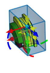
Upon applying the section, the portion of the model pointed by manipulator's arrows will remain visible, while the other portion will be omitted.
See Also: