3D Section by Plane Angle and Octant |
  
|
3D section by plane angle can be created using the following option available in the ![]() 3D Section command's parameters window:
3D Section command's parameters window:
|
Create Section by Plane Angle |
A section of this type cuts-off portion of a model located by one side of an angle formed by two planes. The angle value may be arbitrary.
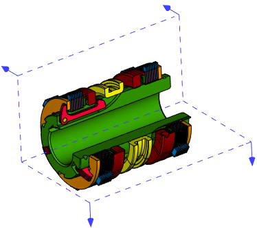
3D section by octant can be created using the following option available in the ![]() 3D Section command's parameters window:
3D Section command's parameters window:
|
Create Section by Octant |
A section of this type cuts-off portion of a model located by one side of a normal angle formed by three planes
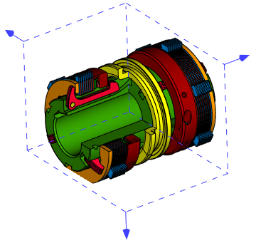
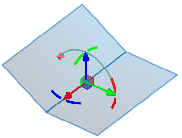
When creating sections by plane angle and octant, positions of cutting planes, view direction and angle value (for plane angle) are defined using special manipulators. Dimensions of cutting planes are symbolic. They're used only for displaying the section in 3D scene, without affecting the result of applying the section. A model is cut by infinite planes. Displayed dimensions of cutting planes are set arbitrarily by the system.
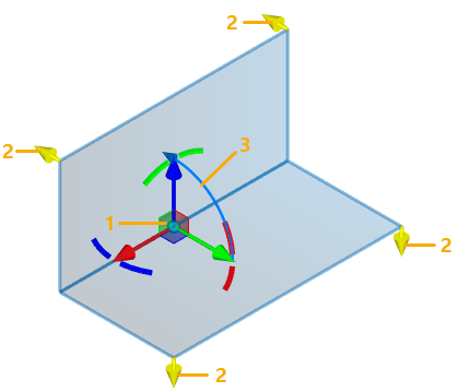
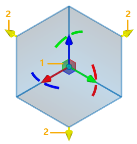
1 - LCS manipulators (defines position of cutting planes)
2 - View direction manipulators
3 - Angle manipulator
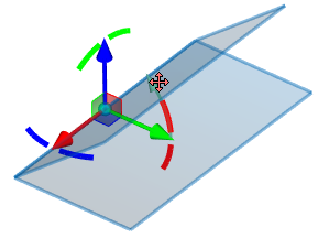
Position of cutting planes is defined using the LCS manipulator similar to the one used for transformations of 3D elements. For section by octant, all cutting planes coincide with planes of the manipulator. For section by plane angle, one of the cutting planes coincides with the XY plane of the manipulator, while the other plane passes through the X axis and is rotated above this axis by an arbitrary angle (90° by default) in relation to the first plane. By default, position and orientation of LCS manipulator coincide with the global coordinate system of the document. You can apply any transformations to the LCS manipulator if necessary. The list of applied transformations is displayed in the Transformations tab of the command's parameters window. The transformations are applied in the same way as in the ![]() Transformations command (see the Types of Transformations of 3D Elements section). The difference is, that for section you get less transformation types available and less options in manipulators' contextual menus. Using the transformations, the position and orientation of manipulator can be linked to various 3D objects.
Transformations command (see the Types of Transformations of 3D Elements section). The difference is, that for section you get less transformation types available and less options in manipulators' contextual menus. Using the transformations, the position and orientation of manipulator can be linked to various 3D objects.
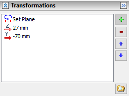
The following option can be used for coinciding the LCS manipulator with any existing coordinate system:
|
<F> |
Select coordinate system |
Activating this option enables in the Filter Toolbar the filter for selecting coordinate systems, so you can select a desired system in 3D scene or in model tree via ![]() .
.
Following options can be used for quick rotation of LCS manipulator by 90° around one of its axes:
|
<X> |
Rotate LCS around X by 90° |
|
<Y> |
Rotate LCS around Y by 90° |
|
<Z> |
Rotate LCS around Z by 90° |
Default view direction of a section is pointed inside the angle. If necessary, you can change the direction by clicking ![]() a direction manipulator or using the following automenu option:
a direction manipulator or using the following automenu option:
|
<D> |
Switch view direction |
Upon applying the section, the portion of the model pointed by manipulator's arrows will remain visible, while the other portion will be omitted.
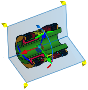
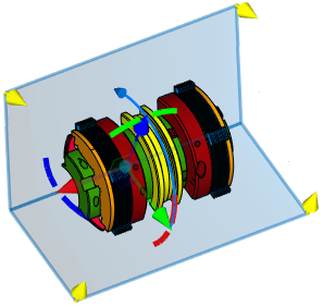
Default plane angle is 90°. You can set an arbitrary angle, if necessary, using the angle manipulator. The angle manipulator is a turquoise arc with an arrow at the tip located in the YZ plane of the LCS manipulator. If you move the cursor over the angle manipulator and press ![]() , then its arrow will start rotating around the X axis of the LCS manipulator in accordance with movement of the cursor, until you press
, then its arrow will start rotating around the X axis of the LCS manipulator in accordance with movement of the cursor, until you press ![]() again. Angle between cutting planes changes in accordance with arrow's position. Value of the angle is displayed in the toolbar at the top of the 3D window
again. Angle between cutting planes changes in accordance with arrow's position. Value of the angle is displayed in the toolbar at the top of the 3D window ![]() . As the manipulator follows the cursor, the keyboard input is focused in this toolbar, so you can type in a value. If the value is typed in via keyboard, then the checkbox near the value gets enabled automatically, so the value no longer depends on the movement of the cursor. Press <Enter> or click
. As the manipulator follows the cursor, the keyboard input is focused in this toolbar, so you can type in a value. If the value is typed in via keyboard, then the checkbox near the value gets enabled automatically, so the value no longer depends on the movement of the cursor. Press <Enter> or click ![]() anywhere within 3D window to confirm the value input.
anywhere within 3D window to confirm the value input.
See Also: