Create Chamfer |
  
|
Main concepts of chamfers are described in the following sections: Chamfer by Length and Angle, Chamfer by Offsets Normal to Faces, Chamfer by Offsets along Faces.
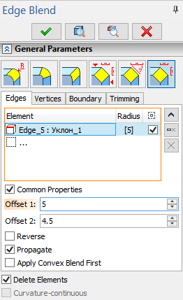
1. Call the mode of creating chamfers by length and angle, by offsets normal to faces, or by offsets along faces.

2. Select edges for chamfering.
3. Define chamfer parameters. The set of parameters is different for various chamfer types. The easiest way to roughly set up parameters values is using manipulators. Exact values can be entered in the Parameters window. Offset 1, Offset 2, Length and Angle values could be entered using keyboard in the corresponding fields located below the list of edges.


The edge direction determines which face correspond to which offset (or length and angle). The edge direction can be flipped using the Reverse checkbox. This checkbox works individually for each edge and does not depend on the Common Properties checkbox.
When defining chamfer by length and angle, the second marker of the manipulator will be driving the Angle parameter. A special checkbox can be enabled against the Angle field that will block angle modification using manipulator. When this checkbox is enabled, both markers of the manipulator drive the Length while keeping the angle fixed.
4. Confirm the operation by ![]() .
.