Boss Smart-fragment Creation Example |
  
|
For convenience, the smart-fragment creation is divided into four stages:
•Modeling body of fitting,
•Modeling body, which defines shape of cutout in pipe,
•Setting parameters of fitting,
•Macro creation
The given example is available in the library ...Examples\3D Modeling\Routing\Gauge boss (Smart).grb
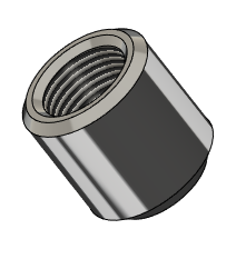
To begin with, you need to create a fragment body. The Rotation and Thread were used to create the boss.
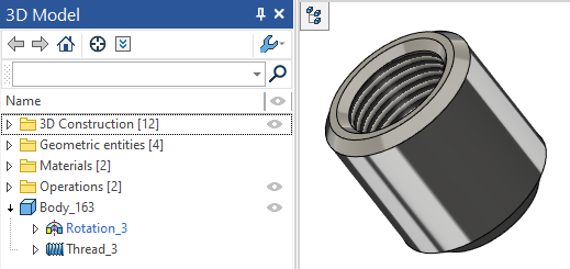
Modeling body, which defines shape of cutout in pipe
The next step is creation of a fitting hole body.
Body for defining an insert in pipe is a fitting element that defines the form and shape of a hole in pipe, in which the fitting is inserted. After insertion, this body disappears.
You need to specify input diameter of main direction fitting DiameterIn1 and main LCS LCS_1 for the boss creation.
More information about variables names can be found in the External Variables of Fitting section. More information about LCS can be found in the LCS and Connector of Fitting section.
Setting Diameter Variable
The diameter is specified in the variables editor. The variable defines diameter of pipe in which the fitting is inserted and specifies fitting location.
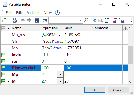
You can set any value for diameter variable. The macro automatically identifies pipe diameter and add its value to the variables, when the fitting is inserted into an assembly.
You need to set External variable flag for the variable.
LCS Creation
Construction line was created in the example to specify LCS location. The line is at distance DiameterIn1/2 from the face of the boss cylindrical part. The pipe diameter is half divided that’s why the boss will be located on the pipe.
|
|
Line that defines LCS location |
Boss location on the pipe |
The LCS should be named LCS_1.
In this case, the fitting will not join any piping elements or other fittings, so the creation of additional connectors (C_In, C_Out), diameters (DiameterIn2, DiameterOut), or their parameters are not required.
Cutout Body Creation
The next step is to create a body to define shape of the cutout in pipe. Contour of the body should follow the shape of the cutout in pipe, so that when you insert fitting there is no intersection of the fitting and the pipe.
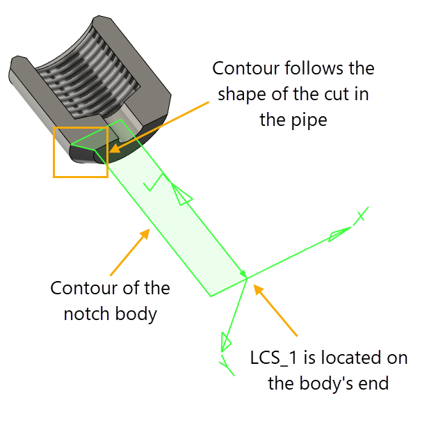
Length of body should depend on LCS_1 position. This is done in order to be able to adjust the position of the fitting on the pipe depending on the pipe diameter.
It is better to have the body with the most simple geometry - a box or cylinder. This will reduce the time of the pipeline regeneration.
If the body is not created, a cutout will have the form of the inserted fragment.
In this case, the body is obtained by rotating profile around axis.
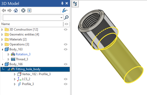
Body to set the shape of cutout in the pipe should be hidden in the 3D scene and on the drawing. In order to hide it you need to do the following:
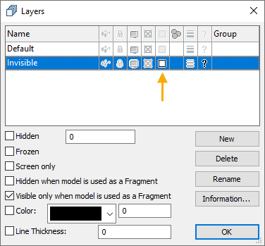
•In the editor of layers, create a new layer, name it Invisible and enable the Visible only when inserted in assembly checkbox for it.
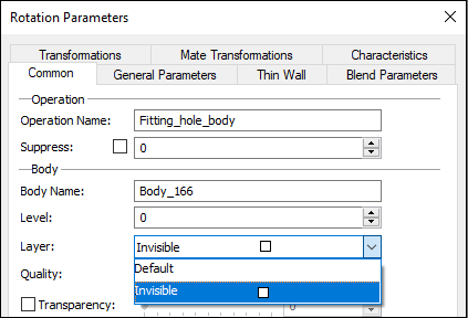
•In the parameters of created body on the General tab, you must specify the previously created layer Invisible, then the body will be hidden in the 3D scene
After creating the fitting body it is necessary to set the parameters for its insertion into assembly as a smart fragment. To do this, use the dialog of the Document Parameters command and go to 3D Fragment tab.
In the window that appears you must set Type of Fragment Insertion to Smart Fragment (macro). System will use macro created in Macro Editor when inserting this body. The macro creation is described further. In the Automatically create Boolean operation section set the Operation Type to Subtraction, so that the body create a cutout in the pipe, and in the drop-down list Create operation with select the name of the body that will be used for Boolean operations: in this case - Fitting_hole_body.
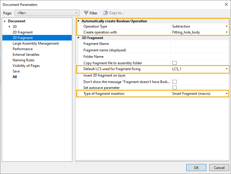
Setting the above parameters allows system to automatically execute macro to create Boolean operation when you insert the smart fragment.
After performing Boolean operation body used as a cutout in the pipe disappears. It will be referenced in the section Pipe Inserts in the parameters window for the selected element of the pipeline.

The following is the sequence of actions to create a macro for inserting a smart fragment:
Use macro editor to create a new macro. Macro text for various fittings differs only in the type indicated in parentheses. In this case the type is Inset.
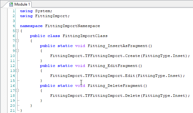
The you need to define three message (event) handlers:
•Inserting as a fragment (Fitting_InsertAsFragment),
•Editing (Fitting_EditFragment),
•Deleting (Fitting_DeleteFragment).
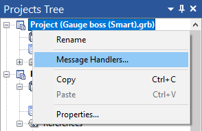
To set the handler you must select the project and from the context menu choose Message Handlers ....
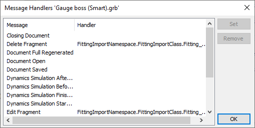
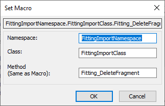
In the window that appears choose one after another three lines Delete Fragment, Edit Fragment, Insert as a Fragment and select them using the macro button Set.
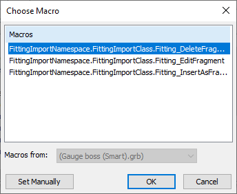
Since the main macro has been previously created in the macro editor, the list will appear from which you can select the desired part of the macro. Macro can be set manually, if necessary, by pressing Set Manually.
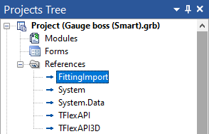
In order to successfully compile the macro add link to FittingImport in the project.
More information about creating macros can be found in the Macros chapter.
After completing all the steps described above, the fragment file must be saved. Now the created fitting can be used for insertion into assembly.